Indicator and signal relays in electrical installations
 In the electricity industry, consumers and sources of electricity are constantly switched both by protection or automation and by operating personnel. All of them require control, accounting, analysis for effective system management.
Algorithm changes that occur in the electrical circuit cannot be captured by human senses. And dispatchers need to know them in a timely manner in order to make correct operational decisions, to ensure continuous and reliable power supply.
For this purpose, special relay structures are used in logic and measurement circuits, which change their initial state when the parameter controlled by them deviates in another device. They are called signal or indicative. Among specialists, another common name for them has been established - blinker.
At first glance, the adjectives "signal" and "indicative" seem to be common synonyms, but they have a small hidden difference.The pointer relay indicates that an operation is taking place in a controlled device, and the alarm relay is usually used in signal circuits to connect various personnel warning systems, for example, light or sound.
Signal relay contacts operate with currents not exceeding two amperes and are used in communication and communication circuits.
The purpose of the indicator relay
Signaling devices allow the duty dispatcher and operatives to monitor the status of other schemes put into operation — protection and automation by:
-
the position of control flags and pointers;
-
light board;
-
sound signals.
The main element providing such information is an intermediate type of indicating relay. It monitors the occurrence of current or voltage in a certain section of the circuit and when it reaches the set value, it trips, throwing out the flag or pointer while simultaneously switching its contacts.
In this position, the triggered element remains as long as operational staff it will not inspect the relay, record the operation performed with a log entry, and only then manually return the device to its initial state.
Thus, the alarm relay has three main tasks:
1. is put into operation during operational switching by connecting the coil to a controlled circuit and mechanically lifting the weight or tensioning the return spring of the signaling mechanism;
2. is triggered when violations occur in the controlled circuit;
3. Return to work only manually and after fixing the attention of the operator.
How indicator relays work
The design of the alarm relay is convenient to compare with the mousetrap device.Both mechanisms have:
-
the drive to be lifted, prepared for further work;
-
a sensitive element that constantly monitors the occurrence of a triggering factor;
-
an executive organ immediately activated by a signal from a sensitive element.
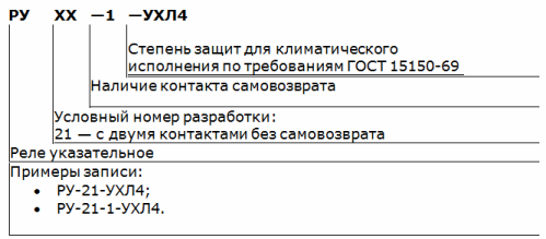
A general view of two types of common indicator, RUE relays on the left and RU-21 on the right, with signal flags activated, is shown in the photo.
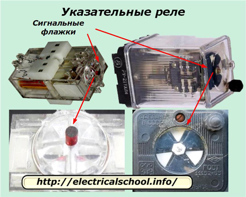
On the left side there is a design where a pointer in the form of a red cylinder emerges from the body, and on the right side an anchor turns and opens white or yellow flags.
Locations of indicator relays
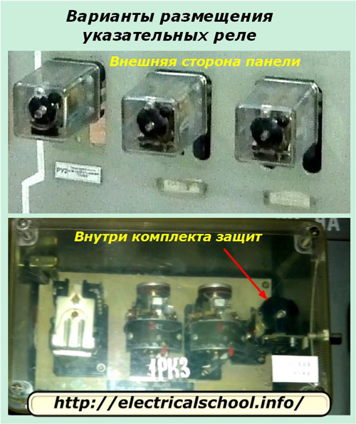
Installation of signaling devices can be carried out:
-
directly on the relay panel at the front, usually at the bottom. The flasher shall be signed with the name of the symbol in the signaling scheme indicating the actuation action of its controlled scheme;
-
inside a set of protections or automation also with a signature.
Design of the indicator relay RU-21 / RU-21-1
An electromagnet is chosen as the basis of the signaling device, which is activated when an electric current passes through its coil. The turns of the coil are located around the conducting core of the magnetic flux.
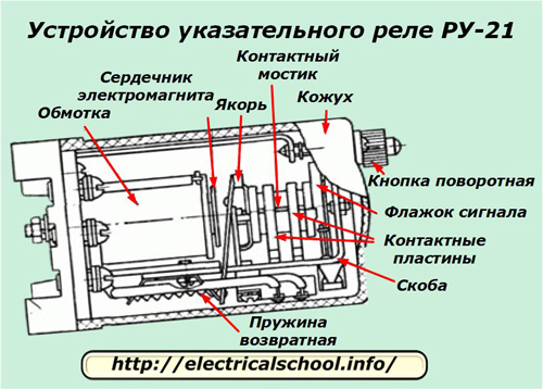
The rotary mechanism makes a limited rotary movement around the horizontal axis. He:
-
made in the form of a drum with a load shifted upwards;
-
placed on two primitive bearings of the simplest construction;
-
equipped with two contact bridges;
-
fixed in the upper raised position with a mechanical lock.
During operation, the movable armature of the electromagnet acquires two positions:
1.when the knob of the protective cover housing is turned by the effort of the operator's hand, the weight mechanism rises up and is fixed with a lock, and the anchor is pulled from the core due to the tension of the return spring;
2. Under the influence of magnetic forces caused by the flow of electric current through the coil of the electromagnet, the armature is attracted to the core. In this case, the latch that holds the rotary mechanism with the contact bridge and signal flag in the upper position is released and the weight falls, turning the rotary mechanism.
This design ensures that the signal flag is released when the solenoid is actuated and retains its position until the operator is tampered with.
Directional relays are designed to operate in AC or DC operating circuits with different standard voltages, for example 220, 110 or 48 volts.
For this purpose, the winding of the coil of the electromagnet is wound with a certain type of wire, strictly observing the calculated cross-section and the number of turns.
A coil designed to operate in current circuits is connected to the break in the wire through which the current flows and is called a series coil. Another principle is used to control the voltage circuits — parallel connection of the coil. Such relays are called parallel coil flashers.
The core of the electromagnet is also made of different constructions that ensure its optimal operation in DC or AC circuits.
The relay body is mounted on a dielectric base to which is attached:
-
bracket for fixing movable mechanisms;
-
protective cover through extension;
-
electromagnet housing;
-
contact screws for connection to the circuit.
This principle of completion of the RU-21 relay may differ slightly in the constructions installed inside the protective kits, when one common protective housing is created, and not several separate ones.
Differences between indicator relays RU-21 and RU-21-1
The RU-21 signal indicators are manufactured for operation on industrial frequency DC or AC circuits, and the RU-21-1 models are for DC circuits only. In addition, their distinguishing feature, characteristic is the presence of additional contact with self-return.
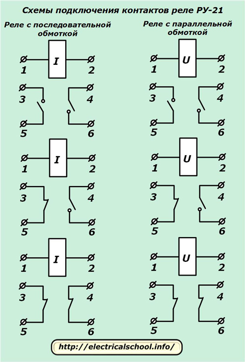
The difference between the electrical circuits of these relays is shown in the photo.
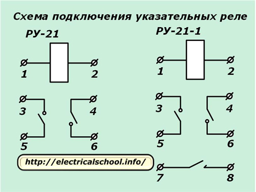
The numbering of the terminal contacts on the base is usually not marked. They can be easily identified by their local position by examining the base on the side of the wiring and counting in the usual way: from left to right and top to bottom, as if reading the text.
Possible schemes for implementing the contact system of the RU-21 relay
The design of the rotary mechanism allows you to change the position of the contact bridges, to rearrange the place of their installation. Due to this, various contact actuation schemes can be created, as shown in the photo.
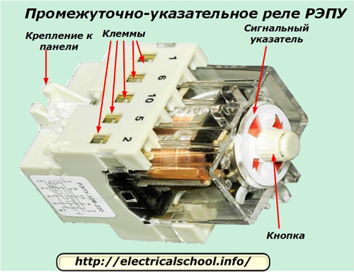
Block diagram of the designation of the indicator relay RU-21
An explanatory transcript is shown below.
Indicator relay
Record examples: RU-21-UHL4, RU-21-1-UHL4.
Design features of the RUE series indication relays
Their mechanism works on the same principles as that of the RU-21 relay. The difference lies in the design of the pointer, which is thrown out of the grip due to the force of the preloaded spring along the axial direction of the relay itself. The cargo mechanism, as in the RU-21, is not used here.
The REU series relays have two main contacts configured to operate either close or open and can be equipped with a self-adjusting contact on some models.
They are made in a transparent plastic housing with the possibility of being attached from the front or back to the panel wall or a general protective casing.
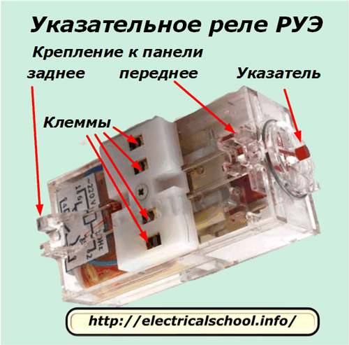
Designs of REPU intermediate indicator relays
They repeat the actuation mechanism of the previous models, but have one or two additional self-setting contacts in their device, which are actuated by a built-in reed switch.
The appearance of the REPU series relay is shown below.
Combined electromagnetic relay with indicating mechanism
Electromagnetic relays equipped with an alarm mechanism can be used in automation devices. Such designs are more common among devices from foreign manufacturers.
A similar scheme is implemented on the RXSF-1 brand relay, manufactured by the well-known company ABB.
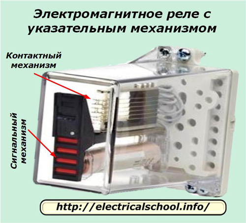
The signaling mechanism flag, red or yellow, falls when the contacts are actuated manually or electrically. It is returned by the operator.
Example of a scheme for switching on signal relays
The practical use of the contact system and the methods of monitoring the electrical signals from relay coils can be different.
One of the options for connecting contacts and coils to the signal circuit of the working circuits of the overhead power line is shown in a fragment of the electrical circuit.
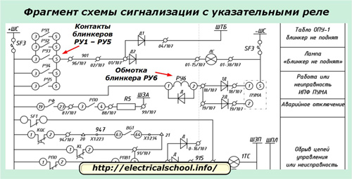
The turn signal coil RU6 is wound in series in the power circuit of the PUMA device between the + SHS and -SHS rails.
Closing contacts 3-5 of five blinkers RU1 ÷ RU5 light up simultaneously:
-
signal lamp LS located on the relay panel;
-
SHTB board located near the dispatcher's workplace to inform him.
By the same principle, sound signals are connected or information is transmitted to distant objects by means of telecommunications.
The overview provided in this article for indicator and signaling relays does not cover all industrial designs. But it allows you to assess the principles of their work, design and methods of practical application.