Optical proximity switches
Optical proximity switches (sensors) are widely used today in many industries where equipment is used for positioning, counting and simply detecting various objects. The use of coding in sensor circuits allows to avoid the external influence of light sources on them and thus protects against false alarms. Sensors in thermal housings are designed for operation at low temperatures.
These devices are electronic circuits that respond to a change in the light flux falling on the receiver, due to which the presence or absence of an object in a certain area of space is recorded. Encoding the light emitted by the source (spatial selection and modulation) improves efficiency and, as mentioned above, negates the effects of interference.
Structurally, the sensor system includes two main functional blocks — the radiation source and its receiver. These can be two separate housings, or one housing for both blocks, depending on the principle of operation of a particular sensor (switch).
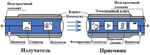
A source or emitter consists of the following parts: a generator, an emitter, an indicator, an optical system and a housing, inside which there is a circuit protected by a joint, and outside - everything necessary for fastening. The task of the generator is to generate a sequence of signal pulses for the emitter.
The emitter itself is an LED. The emission pattern of the LED is formed by the optical system. The indicator shows the presence or absence of power to the sensor. The housing protects against external mechanical influences and serves for convenient installation at the place of application of the sensor.
The receiver, in turn, also has an optical system that forms the directional pattern of the receiver and provides selection. The photodetector that serves phototransistorwhich senses the radiation and converts it into an electrical signal; an amplifier circuit with a threshold element to provide a reliable slope with hysteresis; an electronic switch for switching the load and a regulator for adjusting the sensitivity of the receiver so that objects are recorded clearly against the surrounding background.
There are two indicators here: the first shows the status of the output, the second shows the quality of the received signal and allows you to determine the functional reserve for the monitored object.
In this case, the functional reserve characterizes the ratio of the luminous flux received by the receiver from the emitter to its minimum value, which already causes the operation. The functional reserve compensates for signal attenuation due to contamination of the optics or from disturbing aerosol particles in the surroundings.
For example:
- the indicator lights up red, which means that the tracked object is present in the trigger zone;
- yellow light — the intensity of the received light flux is reduced;
- green — the intensity of the received light flux is minimal;
- off — the object is not in the working area of the sensor.
According to the principle of operation, optical sensors are of three types:
Barrier (Type T)
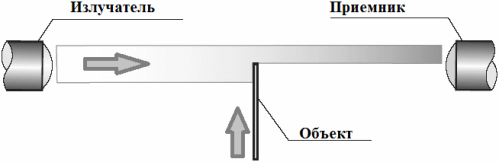
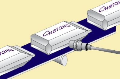
Barrier-type optical switches work on a direct beam and contain two separate parts, a transmitter and a receiver, which must be located coaxially opposite each other so that the radiation flux emitted by the emitter (transmitter) is directed and precisely hits the receiver.
When the beam is interrupted by an object, the switch is triggered. Sensors of this type can work at a distance of tens of meters between the transmitter and the receiver, in addition, they have good noise insulation, they are not afraid of dust, not a drop of liquid, etc.
But there are also disadvantages:
- sometimes it is necessary to lay power wires separately to each of the two parts at long distances;
- highly reflective objects can cause false alarms;
- transparent objects may not weaken the beam enough, this should be taken into account.
The sensitivity regulator is used for acceptable elimination of these shortcomings. And, of course, the minimum size of the detected object should not be less than the diameter of the beam.
Diffuse (Type D)
Diffuse sensors use a beam reflected from an object, a specular reflection. The receiver and transmitter are in one housing. The emitter directs the flow to the object, the beam is reflected from its surface in different directions, depending on the optical characteristics of the object. Part of the flow goes back where it is picked up by the receiver and the switch is actuated.
Here it is important to consider that false alarms can be caused by reflective objects located behind the working area of the installation, behind the controlled object. To eliminate such interference, switches with a background suppression function are used.
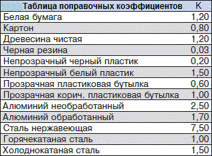
To standardize the distance at which the diffuse sensor will be triggered, take a white sheet of paper (10 by 10 cm for distances up to 40 cm or 20 by 20 cm for detection distances over 40 cm) or a hot-rolled steel plate and test it at similar conditions … In general, in different industries — in different ways.
For more accurate normalization, the distance is recalculated according to a special table that reflects the reflective properties of different materials, and therefore a correction factor is added. For example, a sensor has a value of 100mm, but you want to monitor, say, stainless steel objects.
The correction factor will be 7.5, which means that the safe actuation distance will be 7.5 times greater, namely 750 mm. The smallest object size is determined by its reflective properties, contrast and functional reserve.
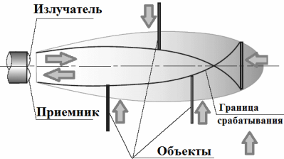
Reflex (type R)
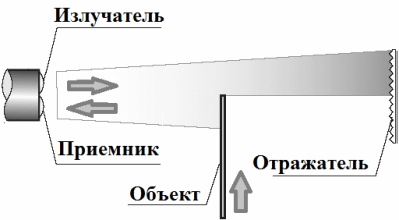
Here the light reflected by the reflector is used. A receiver with an emitter in one housing, the beam falling on the reflector is reflected, strikes the receiver and is triggered. When the object leaves the work area, another trigger occurs. Sensors of this type can work at a distance of up to 10 meters and are used to fix translucent objects.