Phase meters - purpose, types, device and principle of action
 An electrical measuring device is called a phase meter, the function of which is to measure the phase angle between two electrical oscillations of constant frequency. For example, using a phasor meter, you can measure the phase angle in a three-phase voltage network. Phase meters are often used to determine the power factor, cosine phi, of any electrical installation. Thus, phase meters are widely used in the development, commissioning and operation of various electrical and electronic devices and apparatus.
When the phasor is connected to the measured circuit, the device is connected to the voltage circuit and to the current measurement circuit. For a three-phase supply network, the phasor is connected by voltage to three phases, and by current to the secondary windings of current transformers also in three phases.
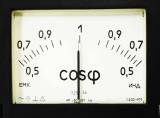
Depending on the device of the phase meter, a simplified scheme of its connection is also possible, when it is also connected to three phases by voltage, and by current - to only two phases.The third phase is then calculated by adding the vectors of only two currents (two measured phases). Purpose of the phase meter — cosine phi measurement (power factor), so in ordinary language they are also called «cosine meters».
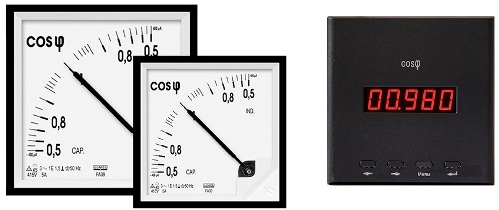
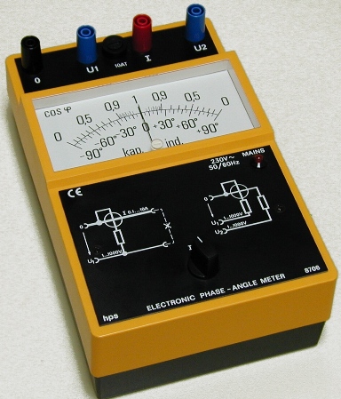
Today you can find phase meters of two types: electrodynamic and digital. Electrodynamic or electromagnetic phase meters are based on a simple scheme with a proportional mechanism for measuring the phase shift. Two frames rigidly attached to each other, the angle between which is 60 degrees, are fixed on the axes in the supports and there is no opposing mechanical moment.
Under certain conditions, which are set by changing the phase shift of the currents in the circuits of these two frames, as well as the angle of attachment of these frames to each other, the movable part of the measuring device is rotated by an angle equal to the phase angle. The linear scale of the device allows you to record the measurement result.
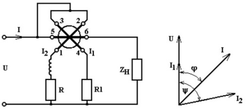
Let's look at the principle of operation of an electrodynamic phase meter. It has a fixed coil of current I and two moving coils. Currents I1 and I2 flow through each of the moving coils. The flowing currents create magnetic fluxes in both the stationary coil and the moving coils. Accordingly, the interacting magnetic fluxes of the coils generate two torques M1 and M2.
The values of these moments depend on the relative position of the two coils, on the angle of rotation of the moving part of the measuring device, and these moments are directed in opposite directions.The average values of the moments depend on the currents flowing in the moving coils (I1 and I2), on the current flowing in the stationary coil (I), on the phase shift angles of the currents of the moving coils relative to the current in the stationary coil (ψ1 and ψ2 ) and on the windings of the design parameters.
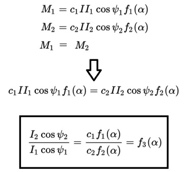
As a result, the movable part of the device rotates under the action of these moments until equilibrium occurs, caused by the equality of the moments resulting from the rotation. The phase meter scale can be calibrated in terms of power factor.
The disadvantages of electrodynamic phase meters are the dependence of the readings on the frequency and the significant consumption of energy from the studied source.
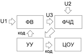
Digital phase meters can be implemented in a variety of ways. For example, a compensation phase meter has a high degree of accuracy even though it is run in manual mode. However, consider how it works. There are two sinusoidal voltages U1 and U2, the phase shift between which you need to know.
The voltage U2 is supplied to the phase shifter (PV), which is controlled by code from the control unit (UU). The phase shift between U3 and U2 is gradually changed until a condition is reached where U1 and U3 are in phase. By adjusting the sign of the phase shift between U1 and U3, the phase sensitive detector (PSD) is determined.
The output signal of the phase sensitive detector is fed to the control unit (CU). The balancing algorithm is implemented using the pulse code method. After the balancing process is completed, the phase shift factor (PV) code will express the phase shift between U1 and U2.
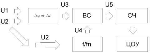
The majority of modern digital phase meters use the principle of discrete counting.This method works in two steps: converting the phase shift into a signal of a certain duration, and then measuring the duration of this pulse using a discrete number. The device contains a phase-to-pulse converter, a time selector (VS), a discrete shaping pulse (f / fn), a counter (MF) and a DSP.
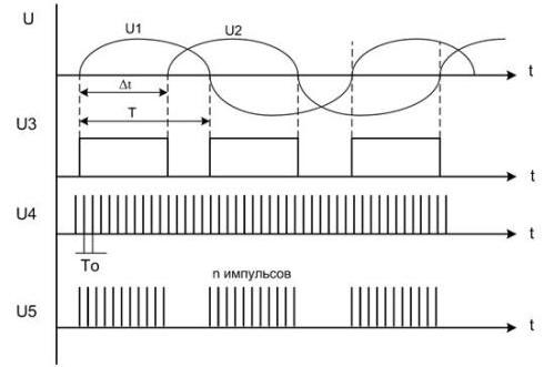
A phase-to-pulse converter is formed from U1 and U2 with a phase shift Δφ rectangular pulses U3 as a sequence. These pulses U3 have a repetition rate and duty cycle corresponding to the frequency and time offset of the input signals U1 and U2. Pulses U4 and U3 form discrete sense pulses of period T0 which are applied to the time selector. The time selector in turn opens for the duration of the U3 pulse and cycles through the U4 pulses. As a result of the output of the time selector, bursts of pulses U5 are obtained, the repetition period of which is T.
The counter (MF) counts the number of pulses in the serial packet U5, with the result that the number of pulses received at the counter (MF) is proportional to the phase shift between U1 and U2. The code from the counter is sent to the central control center, and the readings of the device are displayed in degrees with an accuracy of tenths, which is achieved by the degree of discretion of the device. The discreteness error is related to the ability to measure Δt with an accuracy of one pulse count period.
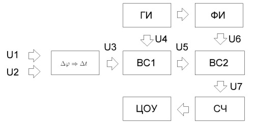
Digital cosine phi averaging electronic phase meters can reduce the error by averaging over several periods T of the test signal.The structure of the digital average phase meter differs from the discrete circuit count by the presence of one more time selector (BC2), as well as a pulse generator (GP) and a discrete pulse generator (PI).
Here, the phase-shift converter U5 includes a pulse generator (PI) and a time selector (BC1). For a calibrated period of time Tk, much larger than T, several packets are fed to the device, at the output of which several packets are formed, this is necessary for averaging the results.
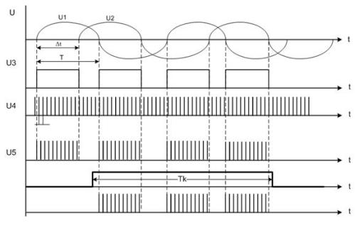
The U6 pulses have a duration that is a multiple of T0, since the pulse shaper (PI) works on the principle of dividing the frequency by a given factor. Signal U6 pulses open the time selector (BC2). As a result, several packets arrive at its input. The U7 signal is fed to the counter (MF) which is connected to the central control center. The resolution of the device is determined by the set of U6.
The error of the phase meter is also affected by the poor accuracy of fixing the phase shift by the converter during the time interval of the moments of transition of signals U2 and U1 through zeros. But these inaccuracies are reduced when averaging the result of calculations for a period Tk, which is much larger than the period of the studied input signals.
We hope this article has helped you gain a general understanding of how phase meters work. You can always find more detailed information in special literature, of which, fortunately, there is a lot on the Internet today.