Encoders — Rotary angle sensors
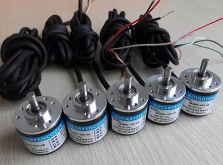
 Positioning in various types of industrial equipment is provided using simple-looking devices — encoders (or in other words, angle sensors).
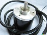
Encoders are used to convert linear or rotary motion into a binary digital signal. An encoder is a device whose shaft is connected to the rotating shaft of the object under study and provides electronic control of the angle of rotation of the latter. According to the principle of operation, encoders are divided into optical and magnetic.
On the shaft of the optical encoder there is a disc with intermittent windows around the perimeter, against which there is an LED and a phototransistor, which ensure the formation of an output signal in the form rectangular pulse trains with a frequency proportional to both the number of windows and the rotational speed of the disk / shaft. The number of pulses indicates the angle of rotation.

Optical encoders are available as incremental and absolute encoders.
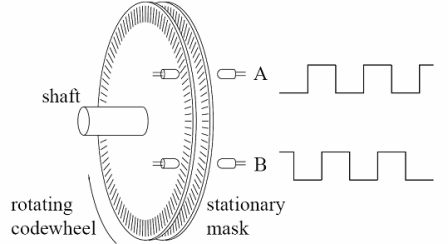
Incremental encoders have an intermittent disc with many windows of the same size as the base radius and two readings optocouplers, which allows you to fix both the angle of rotation and the direction of rotation of the shaft.On the extra radius of the disc there is a single break window and a corresponding optocoupler that define the starting position (home).
Negative Torque - Incremental encoders provide a relative reading of the angle of rotation, information about which is not saved when the rotation is stopped. Their advantages include simplicity of design (and, accordingly, low cost) at high resolution and high operating frequency.
Incremental encoders with increased durability are focused on industrial applications - in mechanical engineering, rolling mills, shipbuilding, textiles, footwear, woodworking. For such encoders, the decisive parameters are the resolution in the angle of rotation, the ability to work at high frequencies, a high degree of protection to withstand the conditions of the harsh environment.
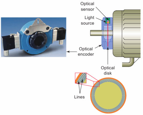
A disc with lines or notches that interrupt the light beam to the optical sensor. An electronic circuit senses the beam breaks and generates digital output pulses from the encoder.
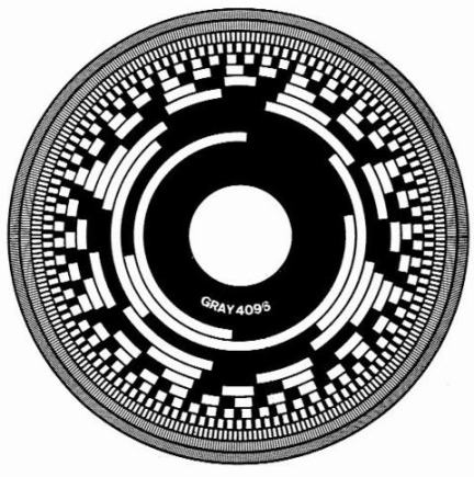
Encoding disk — a device for converting the angular displacements of the shaft into digital form. A geometric image of a digital code is applied to the encoding disk. The code bit symbols are applied on a concentric track, and the least significant (less significant) bits are located closer to the periphery.
Depending on the method of reading the code (contact, photoelectric, electromagnetic, induction, electrostatic, etc.), the geometric image of the code consists of electrically conductive and electrically insulated, transparent and opaque, magnetic and non-magnetic, etc.
The most widespread were encoding disks with varieties of binary code, which exclude the occurrence of errors when crossing the boundaries of separate discrete sections, when some bits can be read on one side of the boundary, and some on the other (due to inaccurate installation of removable devices or due to a non-simultaneous read code while the disk is spinning These codes include the so-called Fau code (Barker code) and Reflex code (Grey code).
Some optical rotary encoders use a reflective encoder disc. This disk has alternating sections that absorb or reflect light, and the light source along with the receiver are located on one side of the disk. If there is only one light source and receiver, the sequence of pulses from the sensor allows you to find out how many steps the disk has rotated relative to its previous position.
A sensor cannot tell the direction of rotation, but if you add a second source-to-receiver pair, 90 out of phase from the first, then the microcontroller will be able to determine the direction of rotation of the disk by the phase difference between the pulse trains.
It should be remembered that any system that detects the relative rotation of the disk but cannot measure its absolute angular position is an incremental encoder.
An absolute encoder has a discontinuous disk with concentric windows of different radii whose relative sizes are determined by the binary code and which are read simultaneously, giving a coded output signal for each angular position (Gray code, binary code...).
In this case, it is possible to obtain data on the instantaneous position of the shaft without a digital counter or return to the initial position, since the output has a coded word — «n bit», protected from electrical noise.
Absolute encoders are used in applications that require storage of input data for a long time, but they are more complex in design and more expensive.
Absolute encoders with a fieldbus interface have an output interface for fieldbus communication in accordance with CANopen, ProfiBus, DeviceNet, Ethernet, InterBus standards and use a binary code to determine the angle of rotation. The above communication interfaces are programmable according to a number of parameters: eg direction of rotation, pulse resolution per revolution, baud rate.
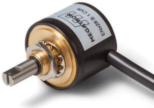
Encoders mounted on the motor shaft effectively provide precise positioning control. Such encoders are usually produced in the «hole» version and special couplings are important elements of their design, which allow to compensate the backlash of the motor shaft.
Positioning under the above conditions most effectively provides a magnetic encoder, in which the conversion of the angular displacement of the shaft into an electronic signal is carried out non-contactly based on the Hall effect, is not related to the rotation of the optical chopper inside the sensor and allows signal processing with speeds up to 60,000 rpm.
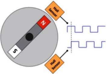
In a magnetic encoder, the high-speed rotation of an external shaft, on which a permanent cylindrical magnet is fixed, is sensed by a Hall sensor combined on a single semiconductor crystal with a signal processing controller.
When the poles of the permanent magnet rotate over the microcircuit with Hall sensor the variable magnetic induction vector induces the Hall voltage, which contains information about the instantaneous value of the shaft rotation angle. The microcontroller provides fast conversion of the Hall voltage to the positioning angle parameter.
The possibility of such conversion without direct mechanical connection of the magnet and Hall sensor elements is the main advantage of magnetic encoders, provides them with high reliability and durability and allows them to work efficiently in high-speed applications related to industrial automation, printing, metalworking, measuring and Measuring Equipment.