Chromatographs and their use in the power industry
The device for chromatographic separation and analysis of mixtures of substances is called a chromatograph... The chromatograph consists of: a sample introduction system, a chromatographic column, a detector, a registration and thermostatic system, and devices for receiving the separated components. Chromatographs are liquid and gas, depending on the aggregate state of the mobile phase. Development chromatography is most often used.
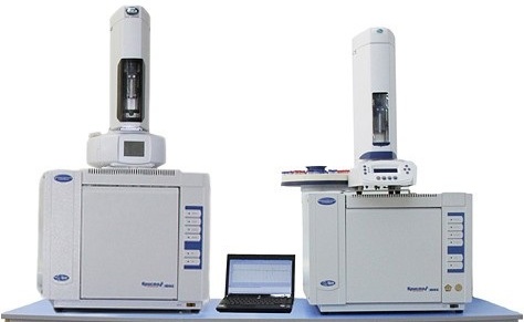
The chromatograph works as follows. The carrier gas is continuously fed from the balloon to the chromatographic column through variable or constant rate pressure and flow regulators. The column is placed in a thermostat and filled with sorbent. The temperature is kept constant and is in the range up to 500 °C.
Liquid and gaseous samples are injected with a syringe. The column separates the multicomponent mixture into several binary mixtures that include both the carrier and one of the analyzed components. Depending on the degree to which the components of the binary mixtures are sorbed, the mixtures enter the detector in a certain order.Based on the detection result, the change in the concentration of the output components is recorded. The processes occurring in the detector are converted into an electrical signal, then recorded in the form of a chromatogram.
In the past ten years, it has become widespread in the power industry. chromatographic analysis of transformer oil, showing good results in the diagnosis of transformers, helping to identify gases dissolved in the oil and to determine the presence of defects in the transformer.
The electrician just takes a sample transformer oil, delivers it to the laboratory, where the employee of the chemical service performs a chromatographic analysis, after which it remains to draw the correct conclusions from the results obtained and decide whether to use the transformer further or if it needs repair or replacement.
Depending on the method of degassing transformer oil, there are several ways to take a sample. Next, let's look at two of the most popular methods.
If degassing is carried out by vacuum, the sample is taken in sealed 5 or 10 ml glass syringes. The syringe is checked for tightness as follows: pull the plunger to the end, stick the end of the needle into the stopper, push the plunger, bringing it to the middle of the syringe, then immerse the stopper with the needle stuck in it, together with the syringe with the plunger half depressed, under water. If there are no air bubbles, the syringe is tight.
The transformer has a branch pipe for oil sampling.The branch pipe is cleaned, a certain amount of stagnant oil is drained, the syringe and oil extraction device are washed with oil, and then a sample is taken. The sampling operation is performed in the following sequence. A tee 5 with a plug 7 is connected to the branch pipe 1 using pipe 2, and pipe 3 is connected to a faucet 4.
The transformer valve is opened, then tap 4 is opened, up to 2 liters of transformer oil are drained through it, and then closed. The needle of the syringe 6 is inserted through the plug 7 of the tee 5 and the syringe is filled with oil. Open valve 4 a little, squeeze oil from the syringe — this is washing the syringe, this procedure is repeated 2 times. Then take a sample of oil in a syringe, remove it from the plug and stick it in a prepared plug.
Close the transformer valve, remove the oil extraction system. The syringe is marked indicating the date, the name of the employee who took the sample, the name of the site, the marking of the transformer, the place where the oil is taken (reservoir, inlet), after which the syringe is placed in a special container, which is sent in the laboratory. Often, the marking is done in abbreviated form, and the decoding is recorded in the log.
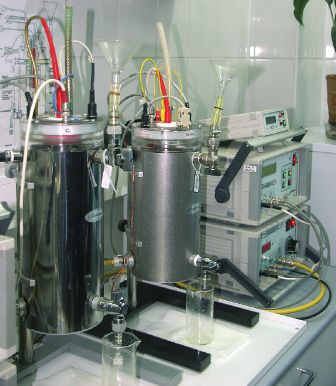
If partial separation of the dissolved gases is planned, the sample is taken in a special oil collector. The accuracy will be higher, but a larger volume of oil will be required, up to three liters. The piston 1 initially sinks to the bottom, the bubble 2, equipped with a temperature sensor 3, with valve 4 closed, is screwed into hole 5, while valve 6 is closed. The plug 8 closes the hole 7 in the lower part of the oil sump.The sample is taken from the nozzle 9, closed with a stopper connected to the transformer pallet. Drain 2 liters of oil.
A pipe with a union nut 10 is attached to the branch pipe. The union with the nut is directed upwards, which allows the oil to drain little by little, no more than 1 ml per second. The bubble 2 turns out and the rod 11 is pressed against the piston 1 through the opening 7, raising it up. Turning the oil collector, the nut 10 is screwed to the hole 5 until the oil stops flowing.
The oil separator is filled with transformer oil at the rate of half a liter per minute. When the handle 12 of the piston 1 appears in the hole 7, the plug 8 is installed in place, at the hole 7. The oil supply is cut off, the hose is not disconnected, the oil collector is turned over, the fitting 10 is disconnected, it is ensured that the oil reaches nozzle 5, bubble 2 is screwed into place, valve 4 must be closed. The oil collector is sent to the laboratory for chromatographic analysis.
Samples are stored until analysis for no more than one day. Laboratory analysis allows obtaining results showing a deviation of the content of dissolved gases from the norm, in connection with which the electrotechnical service decides on the future fate of the transformer.
Chromatographic analysis allows you to determine the content in the dissolved oil: carbon dioxide, hydrogen, carbon monoxide, as well as methane, ethane, acetylene and ethylene, nitrogen and oxygen. The presence of ethylene, acetylene and carbon dioxide is most often analyzed. The smaller the amount of analyzed gases, the less the variety of incipient failures is detected.
Currently, thanks to chromatographic analysis, it is possible to identify two groups of transformer failures:
-
Insulation defects (discharges in paper-oil insulation, overheating of solid insulation);
-
Defects in live parts (overheating of metal, leakage into oil).
Defects of the first group are accompanied by the release of carbon monoxide and carbon dioxide. The concentration of carbon dioxide serves as a criterion for the condition of open-breathing transformers and nitrogen protection of transformer oil. Critical concentration values have been determined, which allow to assess for dangerous defects of the first group; there are special tables.
Defects of the second group are characterized by the formation of acetylene and ethylene in the oil and hydrogen and methane as accompanying gases.
Defects of the first group, associated with damage to the insulation of the windings, represent the greatest danger. Even with a slight mechanical effect on the defect site, an arc can already be formed. Such transformers primarily need repair.
But carbon dioxide can be generated for other reasons that are not related to the failure of the coils, for example, the causes can be aging of the oil or frequent overloads and overheating associated with a failure of the cooling system. There are cases when carbon dioxide mistakenly is fed into the cooling system instead of nitrogen, so it is important to consider the chemical analysis and electrical test data before drawing any conclusions. You can compare the chromatographic analysis data of a similar transformer operating under similar conditions.
During diagnostics, the location of the insulation will be dark brown in color and will clearly stand out against the general background of the entire insulation. Possible traces of leakage on the insulation in the form of branched shoots.
Faults in live connections located close to solid insulation are the most dangerous. An increase in the concentration of carbon dioxide shows that the solid insulation is affected, even more so when comparing the analytical data for a similar transformer. Measure the resistance of the windings, determine the malfunction. Transformers with these defects, as well as with defects of the first group, must be repaired first of all.
In the event that acetylene and ethylene are exceeded at a normal concentration of carbon dioxide, overheating of the magnetic circuit or parts of the structure occurs. Such a transformer needs an overhaul within the next six months. It is important to consider other causes, for example related to a malfunction of the cooling system.
During the repair work of transformers with identified damage of the second group, they find solid and viscous products of oil decomposition at the damage sites, they have a black color. When the transformer is restarted after repair, a quick analysis, within the first month after the repair, will most likely show the presence of previously detected gases, but their concentration will be much lower; the carbon dioxide concentration will not increase. If the concentration starts to increase, the defect remains.
Transformers with oil film protection and other transformers for which the analysis does not confirm the suspected damage to the solid insulation shall be subjected to advanced dissolved gas chromatographic analysis.
Damage to solid insulation accompanied by frequent discharges is the most dangerous type of damage. If two or more gas concentration ratios indicate it, further operation of the transformer is risky and is only allowed with the manufacturer's permission, and the defect must not affect the solid insulation.
The chromatographic analysis is repeated every two weeks, and if within three months the ratio of dissolved gas concentrations does not change, then the rigid insulation is not affected.
The rate of change in gas concentration also indicates defects. With frequent discharges into oil, acetylene increases its concentration by 0.004-0.01% per month or more, and by 0.02-0.03% per month-with frequent discharges into solid insulation. When overheating, the rate of increase in the concentration of acetylene and methane decreases, in this case it is necessary to degas the oil and then analyze it once every six months.
According to the regulations, chromatographic analysis of transformer oil must be carried out every six months, and 750 kV transformers must be analyzed two weeks after commissioning.
Laboratory testing of transformer oil for chemical chromatographic analysis
Effective diagnosis of transformer oil by chromatographic analysis allows today to reduce the volume of work on expensive maintenance of transformers in many power systems.It is no longer necessary to disconnect the networks to measure the insulation characteristics, it is enough just to take a sample of the transformer oil.
So, the chromatographic analysis of transformer oil today is an indispensable method for monitoring transformer defects at the earliest stage of their appearance, it allows you to determine the expected nature of the defects and the degree of their development. The condition of the transformer is assessed by the concentrations of gases dissolved in the oil and the rate of their increase, comparing them with the limit values. For transformers with a voltage of 100 kV and above, such an analysis must be performed at least once every six months.
It is the chromatographic methods of analysis that make it possible to assess the degree of deterioration of the insulators, overheating of the current-carrying parts and the presence of electric discharges in the oil. Based on the extent of the expected breakdown of the transformer insulation, based on the data obtained after a series of analyses, it is possible to assess the need to take the transformer out of service and put it in for repair. The earlier the developing defects are identified, the smaller the risk of accidental damage and the smaller the volume of repair work will be.