Condenser motors — device, principle of operation, application
 In this article we will talk about capacitor motors, which are actually ordinary asynchronous motors, differing only in the way they are connected to the network. Let's touch on the topic of capacitor selection, analyze the reasons for the need for an accurate selection of capacity. Let's note the main formulas that will help to roughly estimate the required capacity.
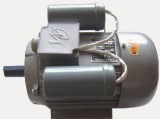
The capacitor motor is called asynchronous engine, in the stator circuit, in which additional capacitance is included to create a phase shift of the current in the stator windings. This often applies to single-phase circuits when three-phase or two-phase induction motors are used.
The stator windings of the induction motor are physically offset from each other and one of them is connected directly to the mains, while the second or second and third are connected to the mains via a capacitor.The capacity of the capacitor is chosen so that the phase shift of the currents between the windings is equal to or at least close to 90 °, then the maximum torque will be provided to the rotor.
In this case, the modules of the magnetic induction of the windings must turn out to be the same, so that the magnetic fields of the stator windings are displaced relative to each other, so that the total field rotates in a circle, and not in an ellipse, dragging the rotor with it with the greatest efficiency.
Obviously, the current and its phase in the coil connected across the capacitor are related to both the capacitance of the capacitor and the effective impedance of the coil, which in turn depends on the speed of the rotor.
When starting the motor, the impedance of the winding is determined only by its inductance and active resistance, so it is relatively small during starting, and here a larger capacitor is needed to ensure optimal starting.
As the rotor accelerates to rated speed, the rotor's magnetic field will induce an EMF in the stator windings, which will be directed against the voltage supplying the winding—the current effective resistance of the winding increases and the required capacitance decreases.
With an optimally selected capacity in each mode (start-up mode, operation mode), the magnetic field will be circular, and here both the rotor speed and the voltage, and the number of windings, and the capacitance connected to the current are relevant. If the optimal value of any parameter is violated, the field becomes elliptical and the motor characteristics decrease accordingly.
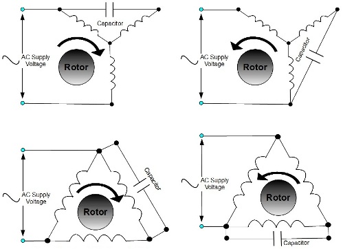
For engines with different purposes, the connection schemes of the capacitor are different.When they are significant Starting torque, use a larger capacity capacitor to ensure optimum current and phase at start-up. If the starting torque is not particularly important, then attention is paid only to creating optimal conditions for the operating mode at the rated speed, and the capacity is selected for the rated speed.
Quite often, for a high-quality start, a start capacitor is used, which is connected in parallel with a running capacitor of relatively small capacity during start-up, so that the rotating magnetic field is circular during start-up, then the start capacitor is turned off and the motor continues to run only with capacitor running. In special cases, a set of switchable capacitors is used for different loads.
If the start capacitor is not accidentally disconnected after the motor reaches the rated speed, the phase shift in the windings will decrease, will not be optimal and the stator magnetic field will become elliptical, which will degrade the performance of the motor. It is imperative that you select the correct starting and operating capacity for the engine to run efficiently.
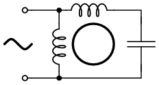
The figure shows typical capacitor motor switching schemes used in practice. For example, consider a two-phase squirrel-cage motor whose stator has two windings to supply two phases A and B.
Capacitor C is included in the circuit of the additional phase of the stator, therefore currents IA and IB flow in the two windings of the stator in two phases. Through the presence of capacitance, a phase shift of currents IA and IB of 90 ° is achieved.
The vector diagram shows that the total current of the network is formed by the geometric sum of the currents of the two phases IA and IB. By choosing the capacitance C, they achieve such a combination with the inductances of the windings that the phase shift of the currents is exactly 90 °.
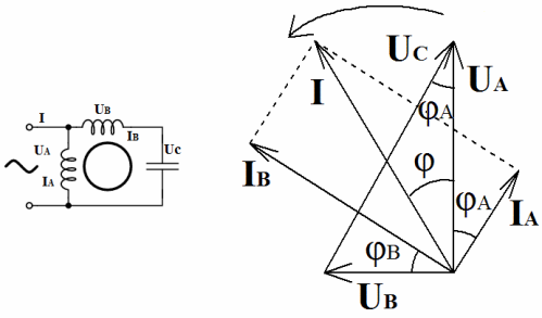
The current IA lags behind the applied line voltage UA by an angle φA, and the current IB lags behind the voltage UB applied to the terminals of the second winding at the current moment by an angle φB. The angle between the mains voltage and the voltage applied to the second coil is 90 °. The voltage on the capacitor USC forms an angle of 90 ° with the current IV.
The diagram shows that full compensation of the phase shift at φ = 0 is achieved when the reactive power consumed by the motor from the network is equal to the reactive power of the capacitor C. The figure shows typical circuits for including three-phase motors with capacitors in the winding circuits of the stator.
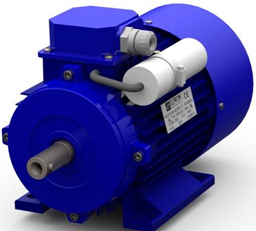
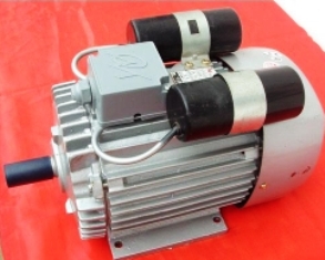
Industry today produces capacitor motors based on two-phase. Three-phase are easily modified manually to supply from a single-phase network. There are also small three-phase modifications, already optimized with a capacitor for a single-phase network.
These solutions are often found in household appliances such as dishwashers and room fans. Industrial circulation pumps, fans and flues also often use capacitor motors in their operation. If it is necessary to include a three-phase motor in a single-phase network, a capacitor with a phase shift is used, that is, the motor is again converted into a capacitor.
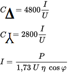
To approximately calculate the capacity of a capacitor, known formulas are used, in which it is enough to substitute the supply voltage and the operating current of the motor, and it is easy to calculate the required capacity for star or delta connection of windings.
To find the operating current of the motor, it is enough to read the data on its nameplate (power, efficiency, cosine phi) and also substitute it in the formula. As a starting capacitor, it is customary to install a capacitor twice the size of the working capacitor.
The advantages of capacitor motors, in fact — asynchronous, include mainly one — the possibility of connecting a three-phase motor to a single-phase network. Among the disadvantages are the need for optimal capacity for a specific load and the inadmissibility of power supply from modified sine wave inverters.
We hope that this article was useful to you, and now you understand what capacitors for asynchronous motors are and how to choose their capacity.