Classification of electrical measuring instruments, instrument scale symbols
In order to control the correct operation of electrical installations, test them, determine the parameters of electrical circuits, record the electrical energy consumed, etc., various electrical measurements are made. In communication technology, as in modern technology, electrical measurements are essential. The devices with which various electrical quantities are measured: current, voltage, resistance, power, etc., are called electrical measuring instruments.
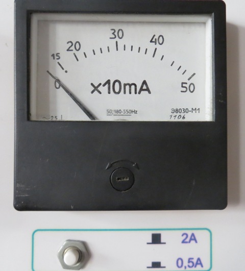
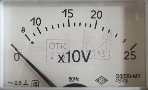
Panel ammeter:
There are a large number of different electrical meters. The following are most often used in the production of electrical measurements: ammeters, voltmeters, galvanometers, wattmeters, electrical measuring devices, phase meters, phase indicators, synchroscopes, frequency meters, ohmmeters, megohmmeters, ground resistances, capacitance and inductance meters, oscilloscopes, measuring bridges, combination tools and measuring sets.
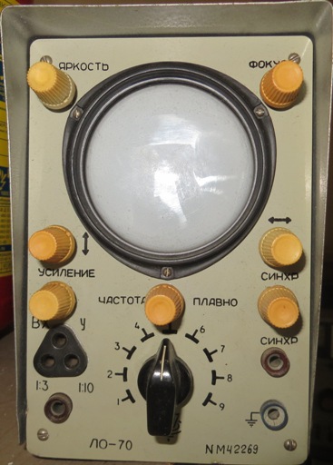
Oscilloscope:
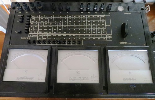
Electrical measuring set K540 (includes voltmeter, ammeter and wattmeter):
Classification of electric tools according to the principle of operation
According to the principle of operation, electrical measuring devices are divided into the following main types:
1. Devices of the magnetoelectric system based on the principle of interaction of the coil with a current and an external magnetic field created by a permanent magnet.
2. NStools for an electrodynamic system based on the principle of electrodynamic interaction of two coils with currents, one of which is stationary and the other is movable.
3. Devices of the electromagnetic system, in which the principle of interaction of the magnetic field of a stationary coil with a current and a movable iron plate magnetized by this field is used.
4. Thermomeasuring devices using the thermal effect of electric current. The wire heated by the current extends, hangs down, and as a result, the movable part of the device can be rotated under the action of the spring, which removes the resulting slack in the wire.
5. Devices of the induction system, based on the principle of interaction of a rotating magnetic field with currents induced by this field in a movable metal cylinder.
6. Electrostatic system devices based on the principle of interaction of movable and immovable metal plates charged with opposite electric charges.
7. Thermoelectric system devices which are a combination of a thermocouple with some sensitive device such as a magnetoelectric system. The measured current passing through the thermocouple contributes to the appearance of a thermal current acting on the magnetoelectric device.
8.Vibration system devices based on the principle of mechanical resonance of vibrating bodies. At a given current frequency, one of the armatures of the electromagnet vibrates most intensively, whose period of natural oscillations coincides with the period of imposed oscillations.
9. Electronic measuring devices - devices whose measuring circuits contain electronic components. They are used to measure almost all electrical quantities, as well as non-electrical quantities that have been converted to electrical.
According to the type of reading device, analog and digital devices are distinguished. In analog instruments, the measured or proportional value directly affects the position of the moving part on which the reading device is located. In digital devices, the moving part is absent and the measured or proportional value is converted to a numerical equivalent recorded with a digital indicator.
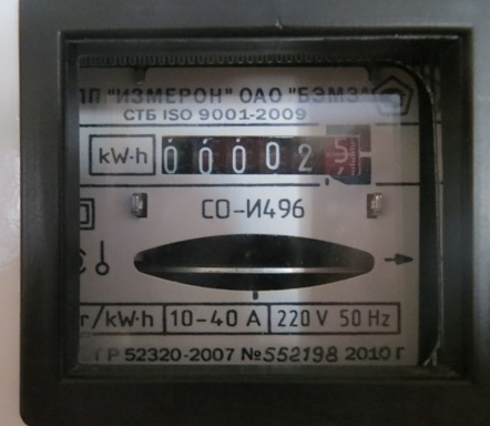
Induction meter:
The deflection of the moving part in most electrical measuring mechanisms depends on the values of the currents in their windings. But in cases where the mechanism must serve to measure a quantity that is not a direct function of the current (resistance, inductance, capacitance, phase shift, frequency, etc.), it is necessary that the resulting torque depends on the measured quantity and independent of supply voltage.
For such measurements, a mechanism is used, the deviation of the moving part of which is determined only by the ratio of the currents in its two windings and does not depend on their values. Devices built according to this general principle are called ratios.It is possible to construct a ratiometric mechanism of any electrical measuring system with a characteristic feature — the absence of a mechanical counteracting moment created by torsion of springs or striae.
Voltmeter legend:
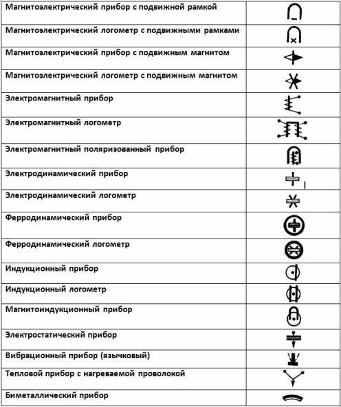
The figures below show the symbols of electrical meters according to their principle of operation.
Determination of the principle of operation of the device
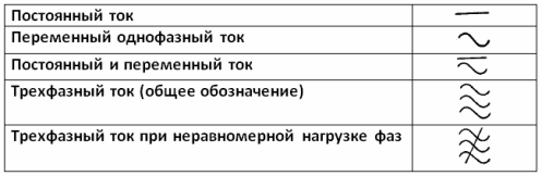
Current type designations
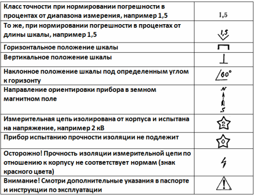
Designations for accuracy class, device position, insulation strength, influencing quantities
Classification of electrical measuring devices according to the type of measured quantity
Electrical meters are also classified according to the nature of the quantity they measure, since instruments with the same principle of operation, but designed to measure different quantities, can differ greatly from each other in their construction, not to mention scale on the device.
Table 1 shows a list of symbols for the most common electrical meters.
Table 1. Examples of designation of measurement units, their multiples and subsets
Name Designation Name Designation Kiloampere kA Power factor cos φ Ampere A Reactive power factor sin φ Milliampere mA Theraohm TΩ Microampere μA Megaohm MΩ Kilovolt kV Kilohm kΩ Volt V Ohm Ω Millivolt mV Milliohm mΩ Megawatt MW Microm μΩ Kilowatt Milliweber mWb Watt W Microfarad mF Megavar MVAR Picofarad pF Kilovar kVAR Henry H Var VAR Milhenry mH Megahertz MHz Microhenry µH KHz kHz Temperature scale degrees Celsius o° C Hertz Hz
Degree of phase angle φo
Classification of electrical measuring instruments according to the degree of accuracy
The absolute error of the device is the difference between the reading of the device and the true value of the measured value.
For example, the absolute error of the ammeter is
δ = I — aiH,
where δ (read "delta") — absolute error in amperes, Az — meter reading in amperes, Azd — the true value of the measured current in amperes.
If I > Azd, then the absolute error of the device is positive, and if I < I, it is negative.
A device correction is a value that must be added to the device reading to obtain the true value of the measured value.
Aze = I — δ = I + (-δ)
Therefore, the correction of the device is the value of the rabsolute absolute error of the device, but opposite to it in sign. For example, if the ammeter shows 1 = 5 A, and the absolute error of the device is δ= 0.1 a, then the true value of the measured value is I = 5+ (-0.1) = 4.9 a.
The reduced error of the device is the ratio of the absolute error to the largest possible deviation of the device indicator (nominal reading of the device).
For example, for an ammeter
β = (δ / In) 100% = ((I — INS) / In) 100%
where β — reduced error in percent, In is the nominal reading of the instrument.
The accuracy of the device is characterized by the value of its maximum reduced error. According to GOST 8.401-80, devices are divided into 9 according to the degree of their accuracy classes: 0.02, 0.05, 0.1, 0.2, 0.5, 1.0, 1.5, 2.5 and 4 ,0. For example, if this device has an accuracy class of 1.5, it means that its maximum reduced error is 1.5%.
Electric meters with accuracy classes 0.02, 0.05, 0.1 and 0.2, as the most accurate, are used where very high measurement accuracy is required. If the device has a reduced error of more than 4%, it is considered out of class.
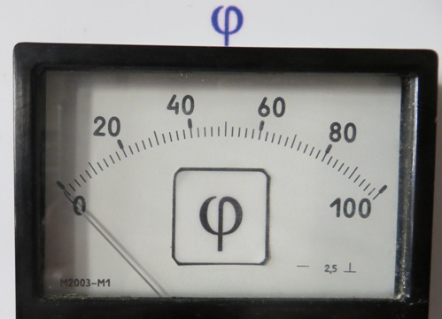
Phase angle measuring instrument with accuracy class 2.5:
Sensitivity and constant of the measuring device
The sensitivity of the device is the ratio of the angular or linear movement of the pointer of the device per unit of the measured value.If the device scale is the same, then its sensitivity over the entire scale is the same.
For example, the sensitivity of an ammeter with the same scale is determined by the formula
S = Δα / ΔI,
where C — ammeter sensitivity in ampere divisions, ΔAz — current increase in amperes or milliamperes, Δα — increase in angular displacement of the device indicator in degrees or millimeters.
If the scale of the device is uneven, then the sensitivity of the device in different areas of the scale is different, since the same increase (for example, current) will correspond to different steps of the angular or linear displacement of the indicator of an instrument.
The reciprocal sensitivity of the instrument is called the instrument constant. The device constant is therefore the unit cost of the device, or, in other words, the value by which the scale reading in divisions must be multiplied to obtain the measured value.
For example, if the constant of the device is 10 mA / div (ten milliamps per division), then when its pointer deviates from α = 10 divisions, the measured current value is I = 10 · 10 = 100 mA.
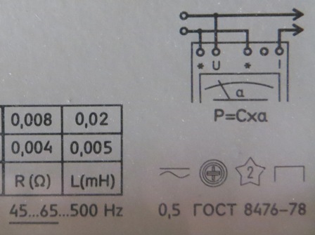
Wattmeter:
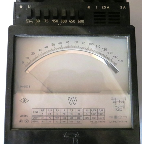
Wattmeter connection diagram and designations of the device (ferrodynamic device for measuring variable and constant power with a horizontal position of the scale, the measuring circuit is isolated from the case and the tested voltage is 2 kV, accuracy class is 0.5):
Calibrating measuring instruments — determining errors or corrections for a set of scale values of an instrument by comparing different combinations of individual scale values with each other. The comparison is based on one of the scale values.Calibration is widely used in the practice of precision metrology work.
The simplest way to calibrate is to compare each size with a nominally equal (reasonably correct) size. This concept should not be confused (as is often done) with the graduation (calibration) of measuring instruments, which is a metrological operation by which the scale divisions of the measuring instrument are given values expressed in certain units of measurement.
Power loss in devices
Electrical measuring devices consume energy during operation, which is usually converted into heat energy. Power loss depends on the mode in the circuit as well as the system and device design.
If the measured power is relatively small, and therefore the current or voltage in the circuit is relatively small, then the power loss of energy in the devices themselves can significantly affect the mode of the circuit under study, and the readings of the devices can have quite a large error. For accurate measurements in circuits where the developed powers are relatively small, it is necessary to know the strength of the energy losses in the devices.
Table 2 shows the average values of energy power losses in different electrical meter systems.
Instrumentation system Voltmeters 100 V, W Ammeters 5A, W Magnetoelectric 0.1 — 1.0 0.2 — 0.4 Electromagnetic 2.0 — 5.0 2.0 — 8.0 Induction 2.0 — 5.0 1 .0 — 4.0 Electrodynamic 3.0 — 6.0 3.5 — 10 Thermal 8.0 — 20.0 2.0 — 3.0