Ammeter and voltmeter device
Initially, voltmeters and ammeters were only mechanical, and only many years later, with the development of microelectronics, digital voltmeters and ammeters began to be produced. Nevertheless, even now mechanical meters are popular. Compared to digital ones, they are resistant to interference and give a more visual representation of the dynamics of the measured value. Their internal mechanisms remain practically the same as the canonical magnetoelectric mechanisms of the first voltmeters and ammeters.
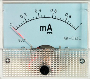
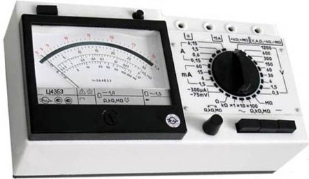
In this article, we will look at the device of a typical dial, so that any beginner can understand the basic principles of operation of voltmeters and ammeters.
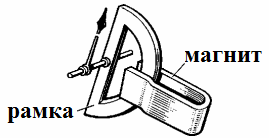
In its work, the pointer measuring device uses the magnetoelectric principle. A permanent magnet with pronounced pole pieces is fixed in place. A steel core is fixed between these poles so that an air gap is formed between the core and the pole parts of the magnet permanent magnetic field.
A movable aluminum frame is inserted into the gap, on which a coil of very thin wire is wound.The frame is fixed on the axle shafts and can be rotated with the pulley. The arrow of the device is attached to the frame with coil springs. A current is supplied to the coil through the springs.
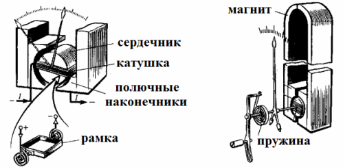
When a current I passes through the wire of the coil, then, since the coil is placed in a magnetic field, and the current in its wires flows perpendicularly, crossing the magnetic field lines in the gap, a rotating force from the side of the magnetic field will act on it. The electromagnetic force will create a torque M, and the coil, together with the frame and the hand, will rotate through a certain angle α.
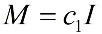
Since the induction of the magnetic field in the gap is unchanged (permanent magnet), the torque will always be proportional to the current in the coil, and its value will depend on the current and on the constant design parameters of this particular device (c1 ). This moment will be equal to:
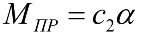
The reaction moment preventing the rotation of the frame, resulting from the presence of springs, will be proportional to the angle of torsion of the springs, that is, the angle of rotation of the arrow connected to the moving part:
In this way, the rotation will continue until the moment M created by the current in the frame is equal to the counter moment Mpr from the springs, that is, until equilibrium occurs. At this point the arrow will stop:
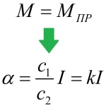
Obviously, the twist angle of the springs will be proportional to the frame current (and the measured current), which is why the magnetoelectric system devices have the same scale. The proportionality factor k between the angle of rotation of the arrow and the unit of the measured current is called the sensitivity of the device.
The reciprocal is called the scale division or unit constant. The measured value is determined as the product of the value divided by number of scale divisions.
In order to avoid disturbing vibrations of the movable frame during the transitions of the arrow from one of its positions to another, magnetic induction or air valves are used in these devices.
The magnetic induction damper is a plate of aluminum that is fixed on the axis of rotation of the device and always moves with the arrow in the field of a permanent magnet. The resulting eddy currents slow down the winding. The conclusion is that, according to Lenz's rule, the eddy currents in the plate, interacting with the magnetic field of the permanent magnet that generated them, impede the movement of the plate, and the oscillations of the arrow quickly die down. The role of such a shock absorber with magnetic induction is played by the aluminum frame on which the coil is wound.
When rotating the frame, the magnetic flux from the permanent magnet penetrating the aluminum frame changes, which means that eddy currents are induced in the aluminum frame, which, when interacting with the magnetic field of the permanent magnet, have a braking effect, and the oscillations of the hand stop.
Air dampers of magnetoelectric devices are cylindrical chambers with pistons placed inside, connected to the moving systems of devices. When the moving part is in motion, the wing-shaped piston is stopped in the chamber and the oscillations of the needle are damped.
In order to achieve the required measurement accuracy, the device must not be affected by gravity during the measurement, and the arrow deflection must be related only to the torque resulting from the interaction of the coil current with the magnetic field of the permanent magnet and with suspension of the frame by means of springs.
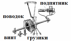
In order to eliminate the harmful effect of gravity and avoid the associated errors, counterweights are added to the moving part of the device in the form of weights moving on rods.
To reduce friction, the steel tips are made of polished wear-resistant steel or tungsten-molybdenum alloy, and the bearings are made of hard mineral (agate, corundum, ruby, etc.). The distance between the tip and the support bearing is adjusted with a set screw.
To accurately set the arrow to the zero starting position, the device is equipped with a corrector. The corrector in the dial is a screw out and connected to a strap with a spring. Using a screw, you can slightly move the spiral along the axis, thereby adjusting the initial position of the arrow.
Most modern devices have a movable part suspended from a pair of stretchers in the form of elastic metal bands that serve to supply current to the coil and create flowing torque. The clamps are connected by a pair of flat springs located perpendicular to each other.
To be honest, we note that in addition to the classic mechanism discussed above, there are also devices with not only U-shaped magnets, but also cylindrical magnets, and prism-shaped magnets, and even with magnets with an internal frame, which themselves may themselves be movable.
To measure current or voltage, the magnetoelectric device is included in the DC circuit according to the ammeter or voltmeter circuit, the difference is only in the resistance of the coil and in the circuit for connecting the device to the circuit. Of course, all the measured current should not pass through the coil of the device when measuring current, and when measuring voltage, not much power should be consumed. An additional resistor built into the housing of the measuring device serves to create suitable conditions.
The resistance of the additional resistor in the voltmeter circuit exceeds the resistance of the coil by many times, and this resistor is made of metal with an extremely small temperature coefficient of resistancesuch as manganin or constantan. The resistor connected in parallel with the coil in the ammeter is called a shunt.
The resistance of the shunt, on the contrary, is several times less than the resistance of the measuring working coil, therefore only a small part of the measured current passes through the coil wire, while the main current flows through the shunt. An additional resistor and shunt allow you to expand the measuring range of the device.
The direction of deviation of the arrow of the device depends on the direction of the current through the measuring coil, therefore, when connecting the device to the circuit, it is important to observe the polarity correctly, otherwise the arrow will move in the other direction. Accordingly, magnetoelectric devices in canonical form are unsuitable for connection to an AC circuit, as the needle will simply vibrate while remaining in one place.
However, the advantages of magnetoelectric devices (ammeters, voltmeters) include high accuracy, uniformity of scale and resistance to disturbances generated by external magnetic fields. The disadvantages are the unsuitability for measuring alternating current (to measure alternating current, you will first need to rectify it), the requirement to observe polarity, and the vulnerability of the thin wire of the measuring coil to overload.