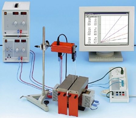
Means and methods for measuring magnetic quantities
Sometimes, to solve technical problems or for research purposes, it is necessary to measure magnetic quantities. Of course, the value of the required magnetic quantity can also be established indirectly by resorting to formulas based on known initial data. However, to obtain the most accurate value of the magnetic flux F, the magnetic induction B or the magnetic field strength H, the direct measurement method is more suitable. Let us consider the methods of direct measurement of magnetic quantities.
In principle, the method of measuring the magnetic value can be based on magnetic field to the current or to the wire. The force caused by the magnetic field is connected to the electrical process, and then with the help of an electrical measuring device, the value of the measured quantity is obtained in a form convenient for human perception.
There are two main methods of measuring magnetic quantities: induction and galvanomagnetic.
The first is based on the induction of EMF when the magnetic flux changes, the second — on the action of the magnetic field on the current. Let's look at these two methods separately.
Method of electromagnetic induction
It is known that when the turns of the coil L are crossed by the magnetic flux F (when the magnetic flux penetrating the circuit changes), an EMF (E) is induced in the coil conductor, proportional to the rate of change of the magnetic flux dF / dt, that is, proportional to its value F. This phenomenon is described by the formula:
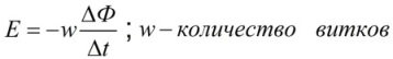
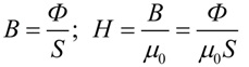
In a uniform magnetic field, the magnetic flux F will be directly proportional to the magnetic induction B, and the coefficient of proportionality will be the area of the loop S pierced by the lines of magnetic induction.
Further on — magnetic induction B will turn out to be directly proportional to the strength of the magnetic field H through the magnetic constant μ0 if the phenomenon occurs in a vacuum, or taking into account the magnetic permeability of the medium — also through the relative magnetic permeability μ of this medium.
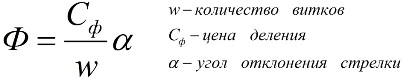
So, the induction method allows you to find the values: magnetic flux Ф, magnetic induction B and magnetic field strength H. Devices for measuring magnetic flux are called webmeters or fluxmeters (from flux — flux).
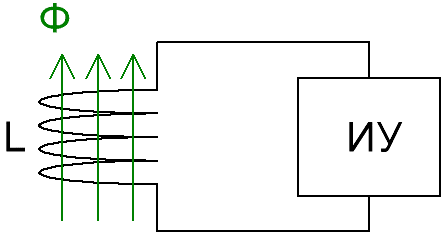
A Webermeter consists of an induction coil with known parameters and a DUT integrator. The integrating device is a magnetoelectric galvanometer.
If the coil of a web meter is brought into or taken out of a space where there is a magnetic field, then the deflection of the measuring mechanism of the web meter (point deflection or change of numbers on the display) will be proportional to the induction B of that magnetic field.The mathematical dependence is easily described by the formula:
Galvanomagnetic method (Hall method)
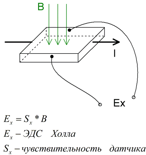
It is well known that Ampere's force acts on a current-carrying wire located in an external magnetic field, and if we look at the process more closely, then Lorentz's force acts on charged particles moving in the wire.
So if a conducting plate is placed in a magnetic field and a direct or alternating electric current passes through the plate, then a direct or alternating potential difference will appear across the ends of the plate. This potential difference Ex is called the Hall EMF.
Based on the known parameters of the plate, knowing the Hall EMF, it is possible to determine the value of the magnetic induction B. A device designed to measure the magnetic induction is called a teslameter.
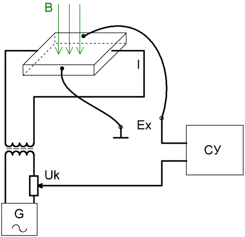
If Hall sensor (Hall sensor) power from one source and then apply a compensating potential difference from a second source, then it is possible to determine the Hall emf by the compensator method using a comparator.
The device is quite simple: the compensating voltage taken from the adjustable resistor is applied in antiphase with the Hall emf and thus the value of the Hall emf is determined. When the compensation circuit and the Hall sensor are fed from the same source, the error that can arise from the instability of the voltage and frequency of the generator is eliminated.
Hall sensors are widely used as rotor position sensors in electric motors and other machines where a signal can be obtained from a moving permanent magnet or from a magnetized transformer core.In particular, the Hall sensor in some applications acts as a kind of alternative to the measuring current transformer.