The principle of operation and types of time relays
For switching electrical circuits in order to implement the operating algorithm of the equipment, in automation schemes and simply for turning on or off with a delay - they are often used time relays... Time relays can be located both on the basis of electronic elements and of electromechanical. In this article we will talk about electronic timing relay circuits that are widespread in today's industry.
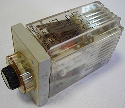
First of all, you need to understand that the time relay creates a certain delay for the operation of direct switching devices, which can be both electronic and mechanical. But the timing relay circuit itself is such an electronic timer.
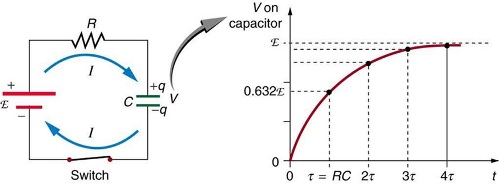
In its simplest form, to set the delay, use an RC circuit, where in the process of charging or discharging a capacitor through a resistor, the voltage in it changes exponentially over time, and a certain RC-circuit has a certain time constant that depends on the resistor and capacitor values in it.
The greater the capacitance of the circuit capacitor and the greater the resistance of the resistor, the longer the process of charging or discharging the capacitor, therefore the longer the capacitor voltage increases or decreases.
In practice, the one-time delay using an RC circuit is limited to 30 seconds, this is due to the final resistance of the printed circuit board, but this limitation does not apply to microcontroller relays, which will be discussed later.
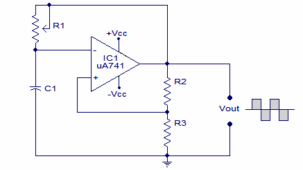
In order not to be limited by the time of a single transition in the RC-circuit, it is necessary to complicate the principle of organizing the delay to some extent, to make the relay multi-cycle, namely to turn the RC-circuit into an RC-generator and then count the pulses from the generator and the pulse duration will again be set to a constant time of the RC circuit in the generator. In this way, the duration of the delay in the time relay can be significantly increased.
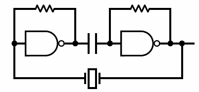
A more accurate result and higher stability will make it possible to obtain an oscillator not of an RC circuit, but of a quartz resonator, because the quartz resonator has a very accurate and stable frequency that does not depend much on the fluctuations of the external temperature, which cannot let's say about capacitors and resistors.
Thus, according to the number of operating cycles, electronic time relays are conditionally divided into multi-cycle and single-cycle.
One-shot timing relay circuit
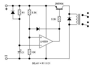
In one-shot circuits, a control signal (such as pressing a button or simply applying power to the circuit) is converted to a matching device where the voltage or current level is converted for processing in the trigger device.
The start device sends a signal to the initial setup device, which in turn starts the executive device or charges the RC-circuit. RC circuits can be switched, thus selecting the delay time from the available range.
In the process of charging (discharging) the capacitor of the circuit, the voltage in it rises (falls) exponentially, while it is continuously compared with the reference voltage of the analog comparator.
As soon as the capacitor voltage goes above (below) the reference voltage, the output converter will start the executive circuit. Obviously, the time interval depends not only on the time constant of the RC-circuit, but also on the value of the reference voltage that is set at the second input of the comparator.
Multi-cycle timing relay circuit
Relay schemes for multi-cycle synchronization allow you to expand the time range, since, as noted above, in multi-cycle schemes, several cycles of operation of the RC circuit or several cycles of operation of the pulse generator are taken into account, i.e. the intervals are longer.
Multi-cycle circuits, like single-cycle ones, receive a signal from the trigger, but this signal goes to the reset block, where it returns the digital part to its initial setting state. The generator is then put into operation, sending a series of pulses to the counter.The number of pulses counted on the counter is compared with the number set on the digital comparator, after reaching the specified number of pulses the output converter is triggered which will start the executive circuit, for example a power contactor.
By changing the frequency of the pulse generator and the value in the digital comparator (or in a simplified version, the output of the counter), the delay time of the time relay is selected. Such blocks can be conveniently implemented on programmable microcontrollers using discrete elements or digital chips.
So, the simplest multi-cycle relay includes the following basic blocks: a digital pulse generator with switching RC-circuits, a pulse counter, a comparator may be absent, and the output of the counter from the selected discharge can be connected directly to a control circuit. By applying "reset" to the digital part, the time relay turns on.
Microcontroller timing relay diagram
Today, microcontroller timing circuits are very common, where many blocks are implemented in software. A quartz resonator is responsible for the clock pulses, and the time setting is set by a block of buttons connected to the corresponding outputs, whose functions are configured in the program as inputs.
At the control output — transistor switch, which controls the executive device. For indication, there is a display where you can personally see how the time counts down.
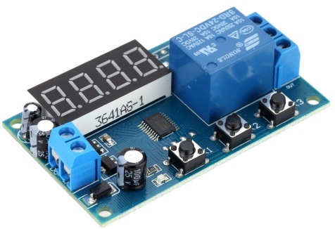
Microcontroller time relays are increasingly popular today due to the low cost of microcontrollers, their small size, and the availability of hardware and software.In addition, microcontrollers consume little electricity, and if such a design is developed on discrete components, then it will turn out to be much more cumbersome and with much more energy.
To change the time relay on a programmable microcontroller, it is enough to update the firmware and you do not need to solder anything. In addition, the digital interfaces of microcontrollers make it easy to pair them with external indicators and keys, as well as with each other and with many blocks of different equipment, not to mention interaction with a computer.
Today's trend is unequivocally aimed at the widespread use of programmable microcontrollers in timing relay circuits and automation both in industrial production and in everyday life.