Resistance thermometers — principle of operation, types and constructions, features of use
One of the most popular types of thermometers in the industry is a resistance thermometer, which is a primary transducer to obtain an accurate temperature value that requires an additional, normalizing converter or an industrial PLC—programmable logic controller.
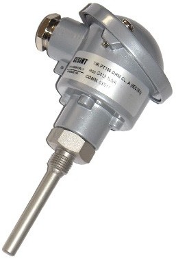
A resistance thermometer is a structure in which a platinum or copper wire is wound on a special dielectric frame, placed inside a sealed protective case, convenient in shape for installation.
The operation of a resistance thermometer is based on the phenomenon of a change in the electrical resistance of a conductor depending on its temperature (from the temperature of the object examined by the thermometer). The dependence of the resistance of the conductor on temperature generally looks like this: Rt = R0 (1 + at), where R0 is the resistance of the conductor at 0 ° C, Rt is the resistance of the conductor at t ° C, and is the temperature coefficient of resistance of the thermosensitive element.
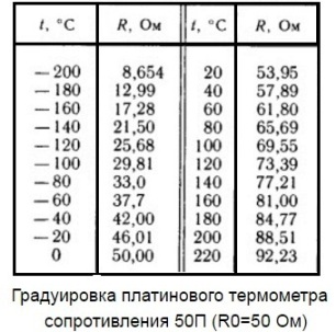
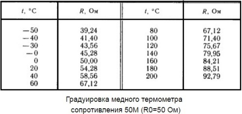
In the process of changing the temperature, the thermal vibrations of the crystal lattice of the metal change their amplitude, and the electrical resistance of the sensor changes accordingly. The higher the temperature—the more the crystal lattice vibrates—the higher the resistance to current. The table above shows the typical characteristics of two popular resistance thermometers.
The sensor's heat-resistant housing is designed to protect it from mechanical damage while measuring the temperature of an object.
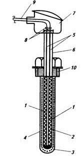
In the photo: 1 — a sensitive element made of platinum or copper wire, in the form of a spiral, located on a ceramic rod; 2 — porous ceramic cylinder; 3 — ceramic powder; 4 — protective outer tube of stainless steel; 5 — current transmission wires; 6 — external protective tube of stainless steel; 7 — thermometer head with removable cover; 8 — terminals for connecting the output wire; 9 — wire to the fixing device; 10 — a threaded sleeve for installation in a pipeline with connections with an internal thread.
If the user has accurately determined the purpose for which a thermal sensor is needed, and has accurately selected a resistance thermometer (resistance thermal converter), then the most important criteria for solving the upcoming task are: high accuracy (about 0.1 ° C) , stability parameters, almost linear dependence of the resistance on a temperature object, interchangeability of thermometers.
Types and design
So, depending on the material from which the sensitive element of the resistance thermometer is made, these devices can be strictly divided into two groups: copper thermal transducers and platinum thermal transducers.Sensors used throughout the territory of Russia and its nearest neighbors are marked as follows. Copper — 50M and 100M, platinum — 50P, 100P, Pt100, Pt500, Pt1000.
The most sensitive Pt1000 and Pt100 thermometers are made by sputtering the thinnest layer of platinum on a ceramic base-substrate. Technologically, a small amount of platinum (about 1 mg) is deposited on the sensitive element, giving the element a small size.
At the same time, the properties of platinum are preserved: linear dependence of resistance on temperature, resistance to high temperatures, thermal stability. For this reason, the most popular platinum resistance transducers are Pt100 and Pt1000. The copper elements 50M and 100M are made by hand winding thin copper wire, and the platinum 50P and 100P by winding platinum wire.
Features of use
Before installing the thermometer, you should make sure that its type is selected correctly, that the calibration characteristic corresponds to the task, that the length of the installation of the working element is suitable, and other design features allow installation in this place, for outdoor conditions.
The sensor is checked for external damage, its body is checked, the integrity of the sensor winding is checked, as well as the insulation resistance.
Some factors can negatively affect the accuracy of the measurement. If the sensor is installed in the wrong place, the length of the installation does not match the working conditions, poor sealing, violation of the thermal insulation of the pipeline or other equipment — all this will cause an error in the temperature measurement.
All contacts must be checked, because if the electrical contact in the connections of the device and the sensor is bad, this is fraught with error. Does moisture or condensation get on the thermometer coil, is there a short circuit, is the connection scheme correct (no compensation wire, no line resistance adjustment), does the calibration of the measuring device match the calibration of the sensor? These are important moments that you should always pay close attention to.
Here are the typical errors that can occur when installing a thermal sensor:
-
If there is no thermal insulation on the pipeline, it will inevitably lead to heat loss, so the temperature measurement location must be selected so that all external factors are taken into account in advance.
-
A short or excessive length of the sensor can contribute to an error due to incorrect installation of the sensor in the working flow of the medium under study (the sensor is not installed against the flow, and not along the axis of the flow, as it should be according to the rules).
-
The sensor calibration does not conform to the prescribed installation scheme in this facility.
-
Violation of the condition for compensating the parasitic influence of the changing ambient temperature (compensating plugs and compensating wire are not installed, the sensor is connected to the temperature recording device in a two-wire circuit).
-
The nature of the environment is not taken into account: increased vibration, chemically aggressive environment, high humidity or high pressure environment. The sensor must meet and withstand the environmental conditions.
- Loose or incomplete contact of the sensor terminals due to poor soldering or due to moisture (no sealing of the wiring from accidental moisture penetration into the thermometer housing).