Ohm's law for a magnetic circuit
If there were no magnetic fluxes, it is unlikely that modern electrical engineering would exist. The operation of generators and electric motors, electromagnets and transformers, measuring instruments and Hall sensors is based on the use of the magnetic field and the properties of the magnetic flux.
To concentrate and strengthen the magnetic flux, they resort to the use of ferromagnetic materials. Ferromagnetic materials are produced magnetic cores — bodies of the required shapes and sizes, cores for directing magnetic fluxes of one or another size in the required direction. Such bodies, inside which closed lines of magnetic induction pass, are called magnetic circuits.
The known properties of the magnetic field make it possible to calculate the magnetic fluxes in various magnetic circuits. But for practical work, it is much more convenient to resort to general consequences and laws of magnetic circuits derived from the laws of the magnetic field, instead of using these laws directly each time. Applying certain rules to magnetic circuits is more convenient for solving typical practical problems.
For example, consider a simple magnetic circuit that consists of an unbranched yoke of cross-section S, which in turn is made of a material with permeability mu… The yoke has a non-magnetic gap of the same area S, for example air, and the magnetic permeability in the gap — mu1 — is different from the magnetic permeability of the yoke. Here you can look at the mean line of induction and apply the magnetic tension theorem to it:
Since the lines of magnetic induction are continuous throughout the circuit, the magnitude of the magnetic flux in both the yoke and the gap is the same. Now we use the formulas for magnetic induction B and for the magnetic flux F to express the strength H of the magnetic field in terms of the magnetic flux F.
The next step is to substitute the resulting expressions into the above formula of the magnetic flux theorem:
We obtained a formula very similar to that known in electrical engineering Ohm's law for a section of a closed circuit, and the role of the EMF here is played by the quantity iN, called the magnetomotive force (or MDF) by analogy with the electromotive force. In the SI system, magnetomotive force is measured in amperes.
The sum in the denominator is nothing more than an analogy of the total electrical resistance for an electric circuit, and for a magnetic circuit it is called the total magnetic resistance accordingly. The terms in the denominator are the magnetic resistances of individual sections of the magnetic circuit.
Magnetic resistances depend on the length of the magnetic circuit, its cross-sectional area, and the magnetic permeability (similar to electrical conductivity for the usual Ohm's law).As a result, you can write the formula of Ohm's law, only for a magnetic circuit:
That is, the formulation of Ohm's law in relation to a magnetic circuit sounds like this: «in a magnetic circuit without branching, the magnetic flux is equal to the quotient of the division of MDS by the total magnetic resistance of the circuit.»
It is obvious from the formulas that the magnetic resistance in NE is measured in weber amperes, and the total magnetic resistance of a magnetic circuit is numerically equal to the sum of the magnetic resistances of the parts of that magnetic circuit.
The situation described is valid for an unbranched magnetic circuit that includes any number of parts, provided that the magnetic flux successively penetrates all these parts. If the magnetic cores are connected in series, then the total magnetic resistance is found by adding the magnetic resistances of the parts.
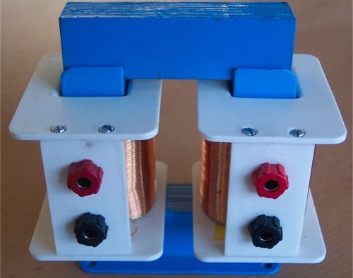
Consider now an experiment that demonstrates the effect of the reluctance of parts of a circuit on the total reluctance of a circuit. A U-shaped magnetic circuit is magnetized by coil 1, which is fed (alternating current) through an ammeter and a rheostat. An EMF is induced in the secondary winding 2, and the readings of the voltmeter connected to the winding, as you know, are proportional to the magnetic flux in the magnetic circuit.
If you now keep the current in the primary winding unchanged by regulating it with a rheostat, and at the same time press the iron plate against the magnetic circuit above, after the total magnetic resistance of the circuit will be greatly reduced, the reading of the voltmeter will increase accordingly.
Of course, the above terms, such as "magnetoresistance" and "magnetomotive force", are formal concepts, since nothing in the magnetic flux moves, there are no moving particles, it is only a visual representation (like a fluid flow model) of a clearer understanding of the laws...
The physical meaning of the above experiment and other similar experiments is to understand how the introduction of non-magnetic gaps and magnetic materials into the magnetic circuit affects the magnetic flux in the magnetic circuit.
By introducing, for example, a magnet into a magnetic circuit, we add additional molecular currents to the bodies already contained in the circuit, which introduce additional magnetic fluxes. Formal concepts such as «magnetic resistance» and «magnetomotive force» prove to be very convenient when solving a practical problem, which is why they are successfully used in electrical engineering.