Main characteristics of the transformer
External characteristics of the transformer
It is known that the voltage across the terminals of the secondary winding transformer depends on the load current connected to that coil. This dependence is called the external characteristic of the transformer.
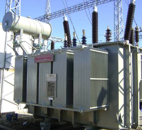
The external characteristic of the transformer is removed at a constant supply voltage, when with a change in the load, in fact with a change in the load current, the voltage at the terminals of the secondary winding, i.e. the secondary voltage of a transformer also changes.
This phenomenon is explained by the fact that on the resistance of the secondary winding, with a change in the load resistance, the voltage drop also changes, and due to the change in the voltage drop across the resistance of the primary winding, the EMF of the secondary winding changes accordingly.
Since the EMF balance equation in the primary winding contains vector quantities, the voltage across the secondary winding depends on both the load current and the nature of that load: whether it is active, inductive, or capacitive.
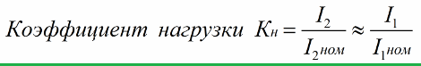
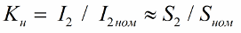
The nature of the load is evidenced by the value of the phase angle between the current through the load and the voltage across the load. Basically, you can enter a load factor that will show how many times the load current differs from the rated current for a given transformer:
To accurately calculate the external characteristics of the transformer, an equivalent circuit can be resorted to, in which, by changing the load resistance, the voltage and current of the secondary winding can be fixed.
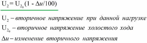
Nevertheless, the following formula proves useful in practice, where the open circuit voltage and the "secondary voltage change", which is measured as a percentage, are substituted and calculated as the arithmetic difference between the open circuit voltage and the voltage at a given load as a percentage of the open circuit voltage:
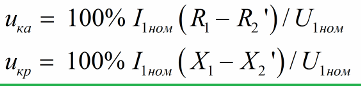
The expression for finding the «secondary voltage change» is obtained with certain assumptions from the equivalent circuit of the transformer:
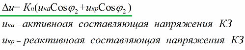
The values of the reactive and active components of the short-circuit voltage are entered here. These voltage components (active and reactive) are found by the equivalent circuit parameters or found experimentally in short circuit experience.
The short circuit experience reveals a lot about the transformer.The short-circuit voltage is found as the ratio of the experimental short-circuit voltage to the rated primary voltage. The "short-circuit voltage" parameter is specified in percent.
In the course of the experiment, the secondary winding is short-circuited to the transformer, while a voltage is applied to the primary much lower than the rated one, so that the short-circuit current is equal to the rated value. Here, the supply voltage is balanced by voltage drop across the windings, and the value of the applied reduced voltage is considered as the equivalent voltage drop across the windings at a load current equal to the rated value.
For low-power supply transformers and for power transformers, the short-circuit voltage value is in the range of 5% to 15%, and the more powerful the transformer, the smaller this value. The exact value of the short-circuit voltage is given in the technical documentation for a specific transformer.
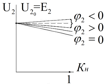
The figure shows the external characteristics built according to the above formulas. We can see that the graphs are linear, this is because the secondary voltage does not depend strongly on the load factor due to the relatively low resistance of the winding, and the operating magnetic flux depends little on the load.
The figure shows that the phase angle, depending on the nature of the load, affects whether the characteristic drops or increases. With an active or active-inductive load, the characteristic drops, with an active-capacitive load it can increase, and then the second term in the formula for "voltage change" becomes negative.
For low-power transformers, the active component usually drops more than the inductive one, so the external characteristic with an active load is less linear than with an active-inductive load. For more powerful transformers it is the opposite, therefore the active load characteristic will be more stringent.
Transformer efficiency
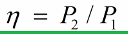
Transformer efficiency is the ratio of the useful electrical power delivered to the load to the active electrical power consumed by the transformer:
The power consumed by the transformer is the sum of the power consumed by the load and the power losses directly in the transformer. Furthermore, active power is related to total power as follows:
Since the output voltage of the transformer is usually weakly dependent on the load, the load factor can be related to the rated apparent power as follows:
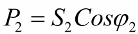
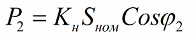
And the power consumed by the load in the secondary circuit:
The electrical losses in the load of arbitrary magnitude can be expressed, taking into account the losses at nominal load, by the load factor:
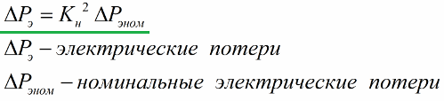
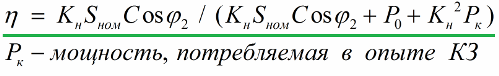
Nominal load losses are determined very precisely by the power consumed by the transformer in the short-circuit experiment, and losses of a magnetic nature are equal to the no-load power consumed by the transformer. These loss components are given in the transformer documentation. So, if we consider the above facts, the efficiency formula will take the following form:
The figure shows the dependence of the transformer efficiency on the load.When the load is zero, the efficiency is zero.
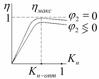
As the load factor increases, the power supplied to the load also increases, and the magnetic losses are unchanged, and the efficiency, which is easy to see, increases linearly. Then comes the optimal value of the load factor, where the efficiency reaches its limit, at this point the maximum efficiency is obtained.
After passing the optimum load factor, the efficiency starts to decrease gradually. This is because electrical losses increase, they are proportional to the square of the current and, accordingly, to the square of the load factor. The maximum efficiency for high power transformers (power is measured in units of kVA or more) is in the range of 98% to 99%, for low power transformers (less than 10 VA) the efficiency can be around 60%.
As a rule, at the design stage they try to make transformers such that the efficiency reaches its maximum value at an optimal load factor of 0.5 to 0.7, then with a real load factor of 0.5 to 1, efficiency will be close to its maximum. With reduction power factor (cosine phi) of the load connected to the secondary winding, the output power also decreases, while the electrical and magnetic losses remain unchanged, hence the efficiency in this case decreases.
The optimal mode of operation of the transformer, i.e. nominal mode, are usually set according to the conditions of trouble-free operation and according to the level of permissible heating during a certain period of operation.This is an extremely important condition so that the transformer, while delivering the rated power while operating in the rated mode, does not overheat.