AC measuring bridges and their use
In AC circuits, bridge circuits are used for measurement purposes. These schemes make it possible to determine the values of capacitors and inductances, tangents of the angle of dielectric losses of the capacitors, as well as the mutual inductances of the coils.
Measuring AC bridges are completely different schemes, they will be discussed below. The most popular are balanced bridges with four arms, where the processes of measuring inductances, capacitances and dielectric loss tangents can be accompanied by compensation of parasitic parameters.
Two groups of AC measurement bridge circuits are particularly expressive: transformer bridges (with inductively coupled arms) and capacitive bridges. Capacitive bridges are circuits with four arms in which capacitive and active elements are installed in the arms. Transformer bridges are characterized by the presence of transformer secondary windings in two arms that serve to power the bridge.
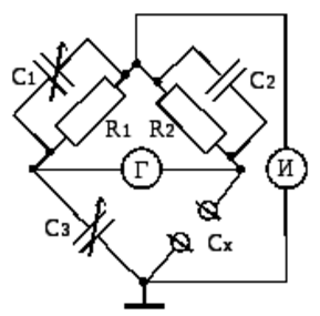
As for capacitive circuits, they can include both constant capacitance and variable (active) resistors, and constant (active) resistors and variable capacitances. A constant capacitance bridge is easier to build as it does not need variable capacitors specially rated, instead there is a sufficient supply of resistors (active resistances).
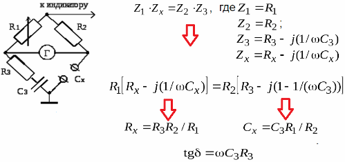
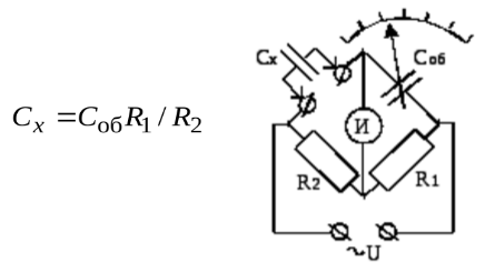
Thanks to the variable resistors, the bridge circuit can be balanced with respect to the reactive and active voltage components. One variable resistor is calibrated according to capacitance values, the other according to dielectric loss tangent values. As a result, an equivalent series circuit of the studied capacitor is obtained. The following equality will reflect this equilibrium state of the bridge, and equating the imaginary and real parts will give only the values of the sought quantities:
But in reality, parasitic parameters always appear and give errors already at audio frequencies. Parasitic inductances, capacitances, conductances are sources of these errors, the accuracy of dielectric loss angle measurement is threatened. Measures to reduce the influence of these factors are the non-inductive and capacitive winding of the first resistor. But in fact it is simply necessary to properly compensate for these influences.
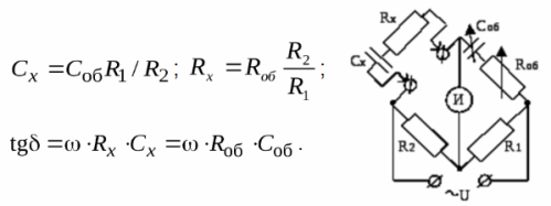
So, to compensate for the parasitic inductance, the trimer capacitor is connected in parallel with the second resistor. In addition, parasitic capacitances and parasitic resistances arise from the presence of insulating parts and the transformer, so it is necessary to double shield the transformer itself.To reduce the effect of capacitance and conductivity of the parts, they are made of high-quality dielectrics, such as fluoroplastic. An audio frequency generator is suitable as a power source.
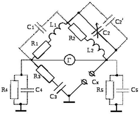
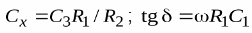
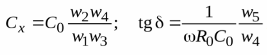
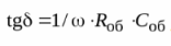
The constant resistances used in bridges provide an advantage: there is no need to calibrate a variable resistor. In the arms, there is only a constant resistance, a constant capacitor and variable capacitors. Measurements of their capabilities are possible directly. The capacitance under study is simply connected to the terminals, after which the bridge is balanced by adjusting the variable capacitors. The calculations are carried out according to the formulas from which it can be seen that the scale for the tangent is obtained directly from the formula with variable capacitance, since the resistance and the frequency are unchanged:
Measuring bridges with inductively connected arms (transformer bridges) are superior to capacitive bridges in a number of aspects: higher sensitivity in terms of tangent and capacitance, low influence of parasitic conductances connected, anyway, in parallel to the arms.
Multi-section transformers can greatly expand the operating range (measuring scale) of the bridge. There are several typical transformer bridge designs, but the most popular is the double transformer bridge:
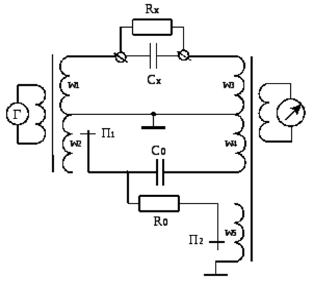
The chain is fully regulated by enumerating the number of turns; it does not need variable capacitors or variable resistors. In this way, it is possible to create meters with a large range of multi-section transformers, and a minimum of sample elements is required.
Here the circuits are galvanically isolated, that is, it is obvious that interference due to parasitic connections is minimal, therefore the connecting wires can be relatively long. The following equations are valid when the bridge is in equilibrium:
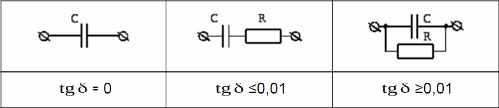
As you know, when it comes to measuring the capacitances of capacitors, active losses in the form of the dielectric loss tangent come to the fore. So, according to this parameter, capacitors are divided into three groups (and the equivalent circuits, respectively, at this frequency differ):
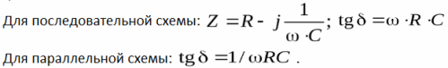
The following ratios reflect the impedance of a capacitor in an AC circuit and its tangent in series and parallel equivalent circuits:
The measurement of the capacitance of a lossless capacitor is carried out according to the following scheme, where two active arms determine the measurement limits by the ratio of their values, and the sample capacitance is variable. Here, in the measurement process, the ratios of the resistors are selected, the value of the sample capacitance is changed. The bridge equilibrium expression is:
Low-loss capacitance measurement is carried out according to the capacitor replacement sequence scheme, while balancing the bridge by changing the capacitance and active resistance, reaching the minimum reading of the zero indicator scale. The equality condition gives the following expressions:
Capacitors with significant dielectric losses require in the equivalent circuit the resistance to be connected in parallel with the sample, according to the above scheme. The formula for the tangent will look like this:
So, using bridges, it is possible to measure the capacitances of real capacitors with nominal values from units of pF to tens of microfarads and with a high degree of accuracy (from 1 to 3 orders of magnitude).
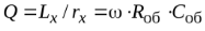
By measuring inductance using the approach described above, it is possible to compare with capacitances and not necessarily with inductances, since creating an accurate variable inductance is not an easy task. So they use sample capacitance equivalent circuits instead of inductors. The equilibrium condition allows you to find resistance and inductance, the result is written in the following form:
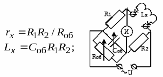
You can also find the Q factor:
Of course, the turn-to-turn capacitance will give small distortions, but these often turn out to be negligible.