Peltier element - how it works and how to check and connect
The principle of operation of the Peltier element is based on on the Peltier effect, which consists in the fact that when a direct electric current passes through a junction of two different conductors, energy is transferred from one transition conductor to another, while heat is released or absorbed at the junction.
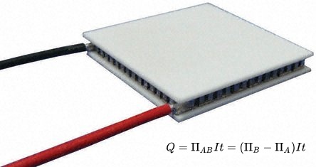
The amount of heat released or absorbed during this process will be proportional to the current, the time of its flow, as well as the Peltier coefficient characteristic of a given pair of soldered wires. The Peltier coefficient, in turn, is equal to the thermoelectric coefficient of the pair multiplied by the absolute temperature of the junction at the current time.
And since the Peltier effect is the most expressive in semiconductors, then this property is used in popular and affordable semiconductor Peltier elements. On one side of the Peltier element heat is absorbed, on the other it is released. Next, we will take a closer look at this phenomenon.
The direct physical effect of Peltier was discovered in 1834.by the French physicist Jean Peltier, and four years later the essence of this phenomenon was investigated by the Russian physicist Emilius Lenz, who showed that if rods of bismuth and antimony were in close contact, water dripped at the point of contact, and then through the junction direct current with a certain direction, then if in the initial direction of the current the water turns into ice, then if the direction of the current changes to the opposite, then this ice will quickly melt.
In his experiment, Lenz clearly demonstrated that Peltier heat is absorbed or released depending on the direction of current through the junction.
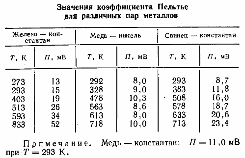
Below is a table of Peltier coefficients for three popular metal pairs. By the way, the effect opposite to the Peltier effect is called the Seebeck effect (when when heating or cooling the junctions of a closed circuit, electricity).
So why does the Peltier effect occur? The reason is that at the point of contact of two substances there is a contact potential difference that generates a contact electric field between them.
If an electric current is now flowing through the contact, this field will either help the current flow or prevent it. Therefore, if the current is directed against the contact field force vector, then the source of the applied EMF must do the work, and the energy of the source is released at the point of contact, this will cause it to heat up.
If the source current is directed along the contact field, then it is, as it were, additionally supported by this internal electric field, and now the field will do additional work to move the charges. This energy is now taken away from the substance, which actually causes the junction to cool.
So, since we know that semiconductor pairs are used in Peltier elements, what process is used in semiconductors?
It's simple. These semiconductors differ in the energy levels of the electrons in the conduction band. When an electron passes through the junction of these materials, the electron gains energy so that it can move to a higher energy conduction band of another semiconductor pair.
When the electron absorbs this energy, the semiconductor contact point cools. When current flows in the opposite direction, the semiconductor contact point heats up, in addition to the usual Joule heat. If pure metals were used instead of semiconductors in Peltier cells, the thermal effect would be so small that ohmic heating would greatly exceed it.
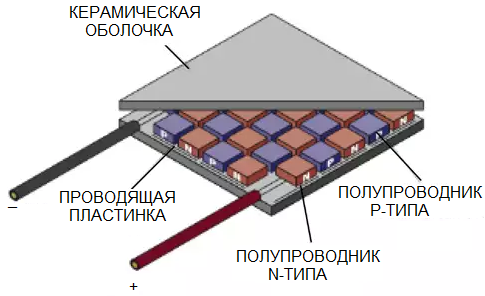
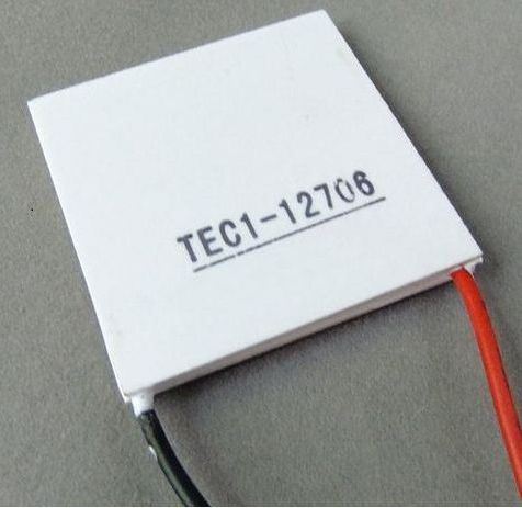
In a true Peltier converter, such as the TEC1-12706, several parallelepipeds of bismuth telluride and solid solution silicon and germanium are mounted between two ceramic substrates, soldered together in a series circuit. These pairs of n- and p-type semiconductors are connected by conductive jumpers that are in contact with the ceramic substrates.
Each pair of small semiconductor parallelepipeds forms a contact to pass current from an n-type semiconductor to a p-type semiconductor on one side of the Peltier converter, and from a p-type semiconductor to an n-type semiconductor on the other side of the converter.
When the current flows through all these series-connected parallelepipeds, then, on the one hand, all the contacts are only cooled, and on the other hand, all are heated only. If the polarity of the source changes, the sides will change their roles.
According to this principle, the Peltier element works, or, as it is also called, the Peltier thermoelectric converter, where heat is taken from one side of the product and transferred to its opposite side, while a temperature difference is created on both sides of the element.
It is even possible to further cool the heating side of the Peltier element using a heatsink with a fan, then the temperature of the cold side will be even lower. In widely available Peltier cells, the temperature difference can reach about 69 °C.
To check the health of the Peltier element, a finger type battery is sufficient. The red wire of the cell is connected to the positive terminal of the power supply, the black wire to the negative. If the element is working correctly, then heating will happen on one side, and cooling on the other, you can feel it with your fingers. The resistance of a conventional Peltier element is in the region of a few ohms.