Basic electrical quantities: charge, voltage, current, power, resistance
Basic electrical quantities: current, voltage, resistance and power.
Charging
The most important physical phenomenon in electrical circuits is motion electric charge… There are two kinds of charges in nature—positive and negative. Like charges attract, like charges repel. This leads to the fact that there is a tendency to group positive charges with negative ones in equal amounts.
An atom consists of a positively charged nucleus surrounded by a cloud of negatively charged electrons. The total negative charge in absolute value is equal to the positive charge of the nucleus. Therefore, the atom has zero total charge, it is also said to be electrically neutral.
In materials that can hold electricity, some electrons are separated from atoms and have the ability to move in a conducting material. These electrons are called mobile charges or charge carriers.
Since each atom in the initial state is neutral, after the separation of the negatively charged electron, it becomes a positively charged ion.Positive ions cannot move freely and form a system of stationary, fixed charges (see — What substances conduct electricity).
In semiconductorsconstituting an important class of materials, mobile electrons can move in two ways: or the electrons simply behave as negatively charged carriers. Or a complex collection of many electrons moves in such a way as if there were positively charged mobile carriers in the material. Fixed charges can be of either character.
Conductive materials can be thought of as materials containing mobile charge carriers (which can have one of two signs) and fixed charges of opposite polarity.
There are also materials called insulators that do not conduct electricity. All charges in the insulator are fixed. Examples of insulators are air, mica, glass, thin layers of oxides that form on the surfaces of many metals, and, of course, a vacuum (in which there are no charges at all).
Charge is measured in coulombs (C) and is usually denoted by Q.
The amount of charge or the amount of negative electricity per electron has been established through numerous experiments and found to be 1.601 × 10⁻¹⁹ CL or 4.803 x 10⁻¹⁰ electrostatic charges.
Some idea of the number of electrons flowing through a wire even at relatively low currents can be obtained as follows. Since the charge of the electron is 1.601 • 10-19 CL, then the number of electrons creating a charge equal to the coulomb is the reciprocal of the given, that is, it is approximately equal to 6 • 1018.
A current of 1 A corresponds to a flow of 1 C per second, and at a current of only 1 μmka (10-12 A) through the cross section of the wire, approximately 6 million electrons per second.Currents of such magnitude are at the same time so small that their detection and measurement are associated with significant experimental difficulties.
The charge on a positive ion is an integer multiple of the charge on an electron, but has the opposite sign. For particles that are singly ionized, the charge turns out to be equal to the charge of the electron.
The density of the nucleus is much higher than the density of the electron. Most of the volume occupied by the atom as a whole is empty.
The concept of electrical phenomena
By rubbing two different bodies together, as well as by induction, the bodies can be given special properties — electrical. Such bodies are called electrified.
The phenomena associated with the interaction of electrified bodies are called electrical phenomena.
The interaction between electrified bodies is determined by the so-called Electric forces that differ from forces of another nature in that they cause charged bodies to repel and attract each other, regardless of the speed of their motion.
In this way, the interaction between charged bodies differs, for example, from the gravitational one, which is characterized only by the attraction of bodies, or from the forces of magnetic origin, which depend on the relative speed of movement of the charges causing magnetic phenomena.
Electrical engineering mainly studies the laws of external manifestation of properties electrified bodies — laws of electromagnetic fields.
Voltage
Because of the strong attraction between opposite charges, most materials are electrically neutral. It takes energy to separate the positive and negative charges.
In fig. 1 shows two conducting, initially uncharged plates spaced apart at a distance d.It is assumed that the space between the plates is filled with an insulator, such as air, or they are in a vacuum.
Rice. 1. Two conductive, initially uncharged plates: a — the plates are electrically neutral; b — charge -Q is transferred to the bottom plate (there is a potential difference and an electric field between the plates).
In fig. 1, both plates are neutral, and the total zero charge on the upper plate can be represented by the sum of charges +Q and -Q. In fig. 1b, the charge -Q is transferred from the upper plate to the lower plate. If in fig. 1b, we connect the plates with a wire, then the forces of attraction of the opposite charges will cause the charge to quickly transfer back and we will return to the situation shown in fig. 1, a. Positive charges would move to the negatively charged plate and negative charges to the positively charged plate.
We say that between the charged plates shown in Fig. 1b, there is a potential difference and that on the positively charged upper plate the potential is higher than on the negatively charged lower plate. In general, there is a potential difference between two points if conduction between those points results in charge transfer.
Positive charges move from a point of high potential to a point of low potential, the direction of movement of negative charges is opposite — from a point of low potential to a point of high potential.
The unit for measuring potential difference is the volt (V). The potential difference is called voltage and is usually denoted by the letter U.
To quantify the tension between two points, the concept is used electric field… In the case shown in fig.1b, there is a uniform electric field between the plates directed from the region of higher potential (from the positive plate) to the region of lower potential (to the negative plate).
The strength of this field, expressed in volts per meter, is proportional to the charge on the plates and can be calculated from the laws of physics if the distribution of charges is known. The relationship between the magnitude of the electric field and the voltage U between the plates has the form U = E NS e (volt = volt / meter x meter).
So, the transition from a lower potential to a higher one corresponds to the movement against the direction of the field. In a more complex structure, the electric field may not be uniform everywhere, and in order to determine the potential difference between two points, it is necessary to repeatedly uses the equation U = E NS e.
The interval between the points of interest to us is divided into many sections, each of which is small enough for the field to be uniform in it. The equation is then applied successively to each segment U = E NS e and the potential differences for each section are summed. Thus, for any distribution of charges and electric fields, you can find the potential difference between any two points.
When determining the potential difference, it is necessary to indicate not only the magnitude of the voltage between two points, but also which point has the highest potential. However, in electrical circuits containing several different elements, it is not always possible to determine in advance which point has the highest potential. To avoid confusion, it is necessary to accept the condition for signs (Fig. 2).
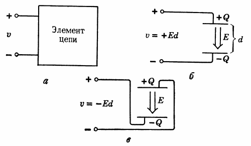
Rice. 2… Determining voltage polarity (voltage can be positive or negative).
A bipolar circuit element is represented by a box equipped with two terminals (Fig. 2, a). The lines leading from the box to the terminals are assumed to be ideal conductors of electric current. One terminal is marked with a plus sign, the other with a minus sign. These characters fix the relative polarity. Voltage U in fig. 2, and is determined by the condition U = (potential of terminal «+») — (potential of terminal «-«).
In fig. 2b, the charged plates are connected to the terminals so that the «+» terminal is connected to the plate with a higher potential. Here the voltage U is a positive number. In fig. 2, the «+» terminal is connected to the lower potential plate. As a result, we get a negative voltage.
It is important to remember about the algebraic form of stress representation. Once the polarity is determined, a positive voltage means that the «+» terminal has a (higher potential) and a negative voltage means that the «-» terminal has a higher potential.
Current
It was noted above that positive charge carriers move from the high potential region to the low potential region, while negative charge carriers move from the low potential region to the high potential region. Any transfer of fees means expiry electricity.
In fig. 3 shows some simple cases of electric current flow, the surface is chosen C and the notional positive direction is shown. If over time dt through the section S, the total charge Q will pass in the chosen direction, then the current I through S will be equal to I = dV/dT. The unit of measurement of current is the ampere (A) (1A = 1C / s).
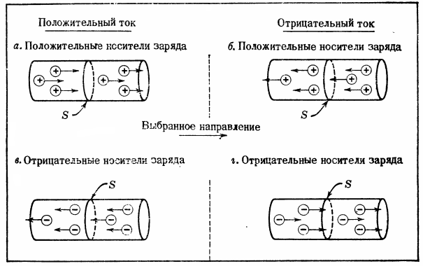
Rice. 3… The relationship between the direction of current and the direction of flow of mobile charges.The current is positive (a and b) if the resulting flow of positive charges through some surface C coincides with the chosen direction. The current is negative (b and d) if the resulting flow of positive charges across the surface is opposite to the chosen direction.
Difficulties often arise in determining the sign of the current Iz. If the mobile charge carriers are positive, then the positive current describes the actual movement of the mobile carriers in the chosen direction, while the negative current describes the flow of mobile charge carriers opposite to the chosen direction.
If the mobile operators are negative, you must be careful when determining the direction of the current. Consider fig. 3d in which the negative mobile charge carriers cross S in the chosen direction. Assume that each carrier has charge -q and the flow rate through S is n carriers per second. During dt is the total passage of charges C in the chosen direction will be dV = -n NS q NS dt, which corresponds to the current I = dV/ dT.
Therefore, the current in Fig.3d is negative. Moreover, this current coincides with the current created by the movement of positive carriers with charge + q through the surface S at a speed of n carriers per second in the direction opposite to the chosen one (Fig. 3, b). Thus, double-digit charges are reflected in the double-digit current. For most cases in electronic circuits, the sign of the current is significant and it does not matter which charge carriers (positive or negative) carry that current. Therefore, often when they talk about electric current, they assume that the charge carriers are positive (see — Direction of electric current).
In semiconductor devices, however, the difference between positive and negative charge carriers is critical to the operation of the device.A detailed examination of the operation of these devices should clearly distinguish the signs of mobile charge carriers. The concept of a current flowing through a certain area can easily be generalized to a current through a circuit element.
In fig. 4 shows a bipolar element. The direction of the positive current is shown by an arrow.
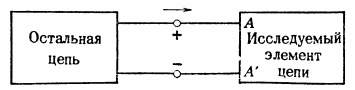
Rice. 4. Current through a circuit element. Charges enter the cell through terminal A at a rate i (coulombs per second) and leave the cell through terminal A' at the same rate.
If a positive current flows through a circuit element, a positive charge enters terminal A at a rate of i coulombs per second. But, as already noted, materials (and circuit elements) usually remain electrically neutral. (Even a "charged" cell in Fig. 1 has zero total charge.) Therefore, if charge flows into the cell through terminal A, an equal amount of charge must simultaneously flow out of the cell through terminal A'. This continuity of electric current flow through the circuit element follows from the neutrality of the element as a whole.
Power
Any bipolar element in a circuit can have a voltage between its terminals and current can flow through it. The signs of current and voltage can be determined independently, but there is an important physical relationship between the polarities of voltage and current, for the clarification of which some additional conditions are usually taken.
In fig. 4 shows how the relative polarities of voltage and current are determined. When the current direction is selected, it flows into the «+» terminal. When this additional condition is met, an important electrical quantity—electrical power—can be determined. Consider the circuit element in Fig. 4.
If the voltage and current are positive, then there is a continuous flow of positive charges from a point of high potential to a point of low potential. To maintain this flow, it is necessary to separate the positive charges from the negative ones and introduce them into the «+» terminal. This continuous separation requires a continuous expenditure of energy.
As charges pass through the element, they release this energy. And since energy must be stored, it is either released in the circuit element as heat (for example, in a toaster) or stored in it (for example, when charging a car battery). The rate at which this energy conversion occurs is called power and is determined by the expression P = U NS Az (watts = volts x amperes).
The unit of measurement of power is the watt (W), which corresponds to the conversion of 1 J of energy into 1 s. Power equal to the product of voltage and current with the polarities defined in fig. 4 is an algebraic quantity.
If P > 0, as in the above case, power is dissipated or absorbed in the element. If P < 0, then in this case the element supplies power to the circuit in which it is connected.
Resistive elements
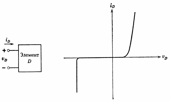
For each circuit element, you can write a specific relationship between the terminal voltage and the current through the element. A resistive element is an element for which the relationship between voltage and current can be plotted. This graph is called the current-voltage characteristic. An example of such a feature is shown in fig. 5.
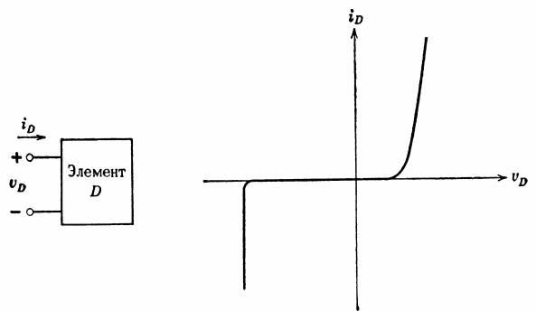
Rice. 5. Current-voltage characteristic of a resistive element
If the voltage at the terminals of element D is known, then the graph can determine the current through element D.Likewise, if the current is known, the voltage can be determined.
Perfect resistance
The ideal resistance (or resistor) is linear resistive element… By definition of linearity, the relationship between voltage and current in a linear resistive element is such that when the current is doubled, the voltage is also doubled. In general, voltage should be proportional to current.
The proportional relationship between voltage and current is called Ohm's law for a section of a circuit and is written in two ways: U = I NS R, where R is the resistance of the element, and I = G NS U, where G = I / R is the conductivity of the element. The unit of resistance is the ohm (ohm), and the unit of conductivity is the siemens (cm).
The current-voltage characteristic of the ideal resistance is shown in Fig. 6. The graph is a straight line through the origin with a slope equal to Az/R.

Rice. 6. Designation (a) and current-voltage characteristic (b) of an ideal resistor.
Power with perfect resistance
Expressing the power absorbed by the ideal resistance:
P = U NS I = I2NS R, P = U2/ R
Just as the power absorbed, in an ideal resistance, depends on the square of the current (or voltage), the sign of the power absorbed v in an ideal resistance depends on the sign of R. Although negative resistance values are sometimes used when simulating certain types of devices operating in certain modes, all real resistances are usually positive. For these resistances, the absorbed power is always positive.
The electrical energy absorbed by the resistance, acc law of conservation of energy, Must NStransform into other species.Most often, electrical energy is converted into heat energy, called Joule heat. Excretion rate joule heat in terms of resistance, it matches the rate of absorption of electrical energy. Exceptions are those resistive elements (for example, a light bulb or speaker), where part of the absorbed energy is converted into other forms (light and sound energy).
Interrelationship of the main electrical quantities
For direct current, the basic units are shown in fig. 7.
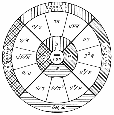
Rice. 7. Interrelationship of the main electrical quantities
Four basic units — current, voltage, resistance and power — are interconnected by reliably established relationships, which allows us to make not only direct, but also indirect measurements or to calculate the values we need from other measured ones. So, to measure the voltage in a part of the circuit, one must have a voltmeter, but even in its absence, knowing the current in the circuit and the current resistance in this section, you can calculate the value of the voltage.