Multi-speed single-phase capacitor motors
Single-phase induction motors are available for operation without speed control. In cases where it is necessary to change the speed, motors with a change in the number of pole pairs are most often used.
In general, 3 different methods can be applied to change the speed of a single-phase motor. One is that the stator contains 2 complete sets of windings, each for a different number of poles. Then, according to Equation 2, different speeds are obtained at the same grid frequency. The other 2 methods are to change the voltage at the motor terminals or to change the number of turns on the main winding by branching from it.
The method based on the use of 2 sets of windings is mainly used for split phase motors and capacitor start motors. Methods based on voltage variation or the use of threaded windings are mainly used for capacitor motors with permanently switched capacitance.
Currently, they are widely used to drive various mechanisms multi-speed asynchronous capacitor motors (electric motors with one constant-on capacity)… This type of electric motors do not require additional elements needed to connect to the network, and also allows you to simply change the direction of rotation of the shaft. To do this, it is enough to change the ends of the main or auxiliary windings in the circuit.
V capacitor motors the basic circuits for turning on the coils shown in fig. 1. The most widespread is the so-called Parallel connection of the windings (Fig. 1, a). As can be seen from the figure, the stator windings are connected in parallel to the power supply. The phase-shifting capacitor C is connected in series with the auxiliary winding.
The value of the capacitance of the capacitor is selected from the conditions for providing the required characteristics of electric motors… In principle, in capacitor motors, the capacitance is chosen so that the phase shift of the currents in the main and auxiliary windings in the nominal mode is close to 90 °. In this case, the engine has the best energy efficiency at the operating point, but the starts deteriorate.
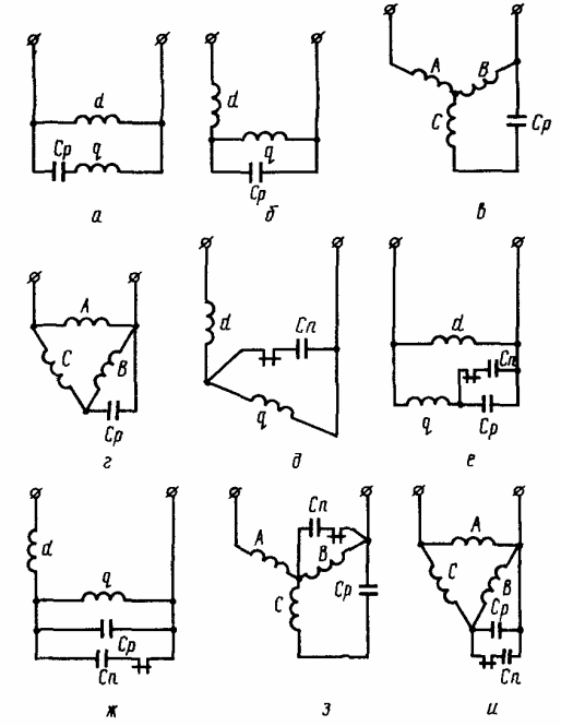
Rice. 1. Schemes for connecting windings of asynchronous motors
The change in the frequency of rotation of capacitor motors is carried out most often by changing the number of pole pairs… For this purpose, either two sets of windings with different numbers of poles, or one set, with a change in the number of poles, are placed on the stator.
In those cases where no significant range of speed control is required, the simplest method is used— change in the number of turns of the working coil… In this case, when the mains voltage remains unchanged, the magnitude of the magnetic flux of the electric motor and, therefore, the electromagnetic moment and the speed of the rotor change.
Two-speed motors with threaded windings
It was previously stated that the speed of a single-phase motor can be changed either by changing the voltage at its terminals or by changing the number of turns of its secondary winding. The first method requires the use of an autotransformer and is mainly used for capacitor motors with permanently on condenser, with shaft fan.
With an autotransformer you can get more than 2 speeds. The change in the number of turns of the main winding is obtained by branching from it. Then the stator has 3 windings: primary, intermediate and auxiliary. The first 2 coils have the same magnetic axis, ie. the intermediate winding is wound in the same slots as the main winding (above it).
The practical implementation of this method is as follows. In the slots of the stator, in addition to the wires of the operating (RO) and capacitor windings (KO), the wires of the additional winding (DO) are laid. As a result of the combination of different winding switching circuits (Fig. 2), it will be possible to obtain different mechanical characteristics of the electric motor with a constant supply voltage.
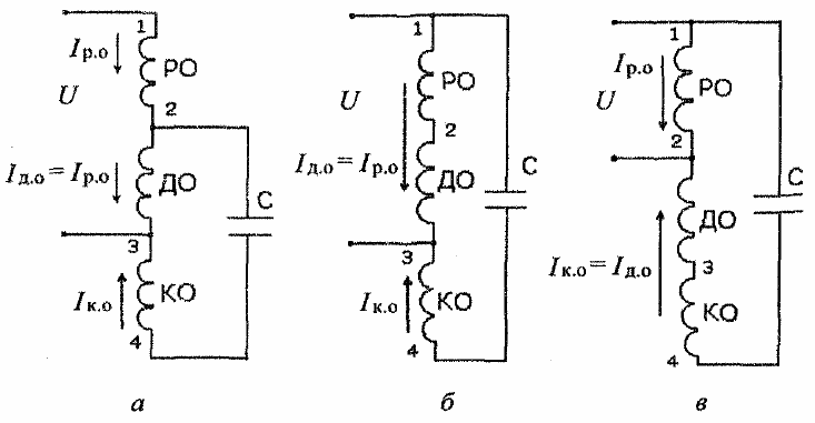
Rice. 2. Connection diagrams of the stator windings of a multi-speed capacitor motor at minimum (a), increased (b) and maximum speed (c)
In the process of adjusting the speed of rotation in multi-speed capacitor electric motors, transient processes occur associated with a change in the switching circuits of the stator windings.These processes occur, as a rule, in continuous magnetic fields and can cause significant inrush currents and overvoltages in the motor windings and the phase-shifting capacitor.
Two speed motors with 2 sets of coils
Placing 2 sets of coils ie. 2 main coils and 2 auxiliary coils, requires a significant increase in size. To reduce these dimensions, an auxiliary or low-speed winding connection is often used, where the number of windings is less than the number of poles.
In fig. 3 shows the connection diagram of the windings for 4 and 6 poles (approximately 1435 and 950 rpm at 50 Hz). Outer winding — 4-pole primary winding. Next is the 6 pole primary winding. The third is a 4-pole auxiliary winding with only 2 groups of windings. The inner coil is a 6-pole auxiliary coil with only 2 groups of coils.
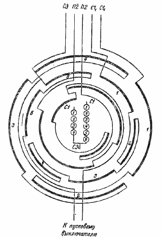
Rice. 3. Wiring diagram of a 2-speed (4 and 6 pole) motor.
In fig. 3 and both auxiliary windings have a reduced number of winding groups. You can also make the main coil of the same type.
Let's look at 2 examples. The stator winding for 4 and 8 poles can have a normal 4-pole main winding and 3 other windings with a reduced number of winding groups, i.e. 8-pole main winding with 4 winding groups, 4-pole auxiliary winding with 2 winding groups and 8 - pole auxiliary winding with 4 winding groups.
The stator winding for 6 and 8 poles can have a normal 6-pole main winding, two 8-pole windings with a reduced number of groups, i.e. 8-pole main winding and 8-pole auxiliary winding with 4-pole groups each, and 6-pole auxiliary winding with 2 winding groups. The 6-pole auxiliary winding can also be designed as a normal winding, i.e.with 6 groups of coils.
In fig. 4 shows a diagram of a 2-stage split-phase motor with 2 windings and also shows the connection to the mains. Connections are made in such a way that only 1 start switch is required. This starting switch should open at 75 to 80% of the synchronous speed of the low speed coil.
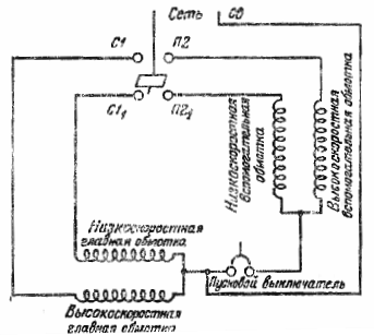
Rice. 4. Diagram of a two-speed split-phase motor
If the scheme shown in fig. 4, is used for a capacitor start motor, then either 1 capacitor connected in series with the start switch or 2 capacitors are used, 1 of which is connected in series with terminal P2 and the other with terminal P21.
If the motor can always be started with a connection matching the same speed, then one of the auxiliary windings can be omitted. In this case, the startup is partially or fully automated.
Multi-speed asynchronous single-phase electric motors DASM
To achieve high speeds in household appliances, electric motors with a high rotor speed ratio are often required. Single-phase capacitor asynchronous motors with 2/12 pole numbers are used for these purposes; 2/14; 2/16; 2/18; 2/24 and even higher.
However, the production of motors with a large pole ratio is technologically difficult, so different types of mechanical speed converters are used, as well as semiconductor frequency converters of the supply voltage.
Most simply, the speed of rotation in small limits for these motors is regulated by changing the supply voltage; for this, additional resistors or chokes are connected in series with the coil.
Back in the USSR two-speed capacitor motors of the DASM-2 and DASM-4 types with 16/2 poles were developed to drive household automatic washing machines.
The DASM -2 engine is designed to drive automatic washing machines with a capacity of 4 — 5 kg of dry linen. It was originally designed for powers of 75/400 W at 390/2750 rpm.
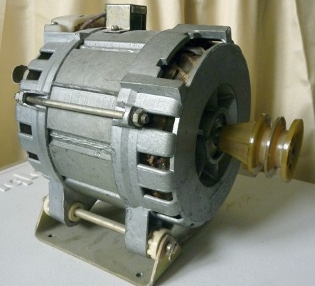
Rice. 5. Two-speed capacitor asynchronous electric motor, type DASM-2
In fig. 5 shows the diagrams for connecting the DASM-2 and DASM-4 engines to the power network. As can be seen from the figure, the DASM-2 motor has four stator windings. The primary and auxiliary windings are connected in parallel.
The DASM-4 motor at low speed is made with a three-phase star connection, and at high speed - with a parallel connection of the stator windings. A temperature relay RK-1-00 is attached to the stator of the motor to protect the windings in overload and short circuit modes. The normally closed relay contacts are connected to the common terminal of the motor stator.
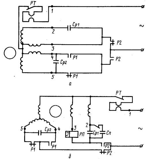
Rice. 5. Schemes for connecting two-speed electric motors to the power supply network: a- DASM-2 electric motor; b — DASM-4 electric motor. I'M GOING. — main winding; V.O, — auxiliary coil; 1 — common output of low and high speed coils; 2 — end of the high-speed auxiliary winding; 3 — the beginning of the main winding at high speed; 4 — the beginning of the low-speed auxiliary winding; 5 — the beginning of the main winding at low speed; Cp — operating capacitor; Cn — starting capacitor; RT-thermal protection relay, type RK-1-00; RP-starting relay, type RTK-1-11; P1, P2 — contacts of the controller.