Tacho generators — types, device and principle of operation
The word "tachogenerator" comes from two words - from the Greek "tachos" meaning "fast" and from the Latin "generator". The tachogenerator is a variable or constant electric measuring micro machine, which is mounted on the shaft of the equipment and converts the current value of the rotation speed of the shaft into an electrical signal, the parameter of which carries information about the rotation frequency.
This parameter can be generated EMF or the frequency value of the signal. The output signal from the tachogenerator may be fed to a visual display (eg a display) or to an automatic shaft speed control device on which the tachogenerator operates.
Tacho generators are of several types, depending on the type of signal generated at the output: with an alternating voltage or current signal (asynchronous or synchronous tachogenerators), or with a constant signal.
DC tachogenerator
A DC tachogenerator is a collector machine with excitation either by permanent magnets (more common) or by an exciting coil (less common) located on its stator. The measuring emf is induced on the rotor winding of the tachogenerator and turns out to be directly proportional to the angular speed of rotation of the rotor, in fact to the rate of change of the magnetic flux, in exact accordance with the law of electromagnetic induction.
The output signal — a voltage whose value is also directly proportional to the angular speed of rotation of the rotor — is removed through the brushes from the collector. Since the job involves collector and brushes, such a unit is subject to faster wear than an AC tachogenerator. The problem is that in the process of its work, the brush-collecting unit generates impulse noise in the output signal of such a tachogenerator.
One way or another, the output signal of the DC tachogenerator is a voltage, which makes it difficult to accurately convert the voltage to speed, because the magnetic deflection flux depends on the temperature of the magnets, on the electrical resistance at the point of contact of the brushes with the collector (which changes with time ), finally — from demagnetization of permanent magnets over time.
Nevertheless, in some cases DC tachogenerators are convenient for the form of representation of the output signal, as well as the natural phenomenon of reversing the polarity of this signal in accordance with the change in the direction of rotation of the shaft.
DC tachogenerators are characterized by a «transformation factor» St, which expresses the ratio of the removed voltage Uout to the rotation frequency Frot corresponding to the given voltage.This parameter is specified in the technical documentation for the tachogenerator and is measured in millivolts multiplied by revolutions per minute. Knowing this parameter and the output voltage from the tachogenerator, you can calculate the current frequency using the formula:
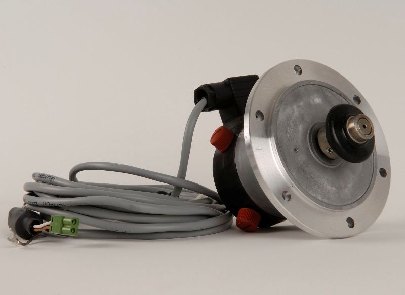
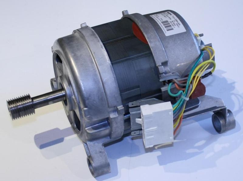
Electric motor with built-in tachogenerator:
Asynchronous AC tachogenerator
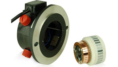
Asynchronous AC tachogenerators are similar in design for asynchronous squirrel-cage motors… The rotor here is made in the form of a hollow cylinder (usually copper or aluminum), and the stator contains two windings located at right angles to each other. One of the stator windings is the excitation winding, the second is the output winding. An alternating current of a certain amplitude and frequency is supplied to the excitation coil, and the output coil is connected to the measuring device.
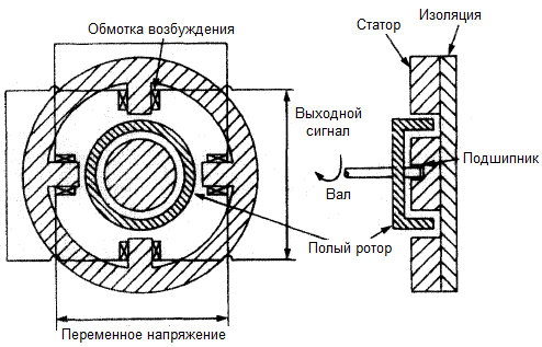
When the squirrel rotor rotates, it periodically breaks the initial orthogonality of the magnetic fluxes of the two coils, as a result of the distortion of the picture of the magnetic fields, an EMF is periodically induced in the output coil. If the rotor is stationary, then the magnetic flux of the excitation coil is not distorted and no EMF is induced in the output coil. Here, the magnitude of the generated EMF is proportional to the speed of rotation of the shaft.
Since the current supplied to the field winding has its own frequency, different from the speed of rotation of the shaft, such a tachogenerator is called asynchronous. Among other things, this design makes it possible to judge the direction of rotation of the rotor by the phase of the output signal — when changing the direction of rotation, the phase is reversed.
Synchronous AC tachogenerator
Synchronous tachogenerators are brushless AC machines.The magnetization of the rotor is created by a permanent magnet while one or more windings are present on the stator. In this case, both the amplitude of the output signal and its frequency will be proportional to the speed of rotation of the shaft. Velocity data can therefore be measured both by amplitude value (amplitude detection) and directly by frequency (frequency detection). However, the direction of rotation cannot be determined from the output signal of the synchronous tachogenerator.

The rotor of a synchronous AC tachogenerator can be made in the form of a multipole magnet and give several pulses in a row in the output signal for one revolution of the shaft. Such tachogenerators, along with asynchronous ones, have a longer service life, since they do not have a brush collection device prone to mechanical wear.
Frequency detection
Since the output frequency of a synchronous tachogenerator does not depend on temperature and other factors, frequency measurements with it are more accurate. The calculation is very simple, it is enough to know the number of pole pairs p of the rotor:
 But there is also a nuance. In order for the accuracy of the calculations to be high enough, it is necessary to allocate time during which theoretically the speed can already change, which means that while the pulses are being counted, the measurement error increases, which is harmful.
To reduce the measurement error, the rotor is made multi-pole so that the calculations can be done faster, then the response of the control system can follow faster. For one pole, the frequency is calculated using the following formula:
where N is the number of pulses read, T is the pulse count period
For a synchronous tachogenerator, the amplitude of the signal changes depending on the speed, therefore, when designing the output frequency detector, it is important to take into account the entire possible range of amplitudes of the output voltages of the tachogenerator.
Amplitude detection
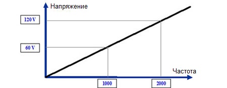
With the amplitude method of determining the frequency, the circuit of the frequency detector will be simpler, but here it is important to take into account the influence of such factors as: temperature, change in the non-magnetic gap, etc. The higher the frequency , the larger the amplitude of the output signal, therefore the detector circuit is usually a rectifier and Low pass filter, where the conversion factor measured in mV * rpm allows you to determine the frequency using the following formula:
In addition to the traditional types of tachogenerators discussed in this article, pulse sensors are also used in modern technologies. based on optocouplers, Hall sensors etc. The advantage of tachogenerators is that when paired with a detector, they do not require any additional power sources. Disadvantages of traditional machine-type tachogenerators include poor sensitivity at low speeds and introduced braking torque.