Electron tubes - history, principle of operation, design, application
Electron tube (radio tube) — a technical innovation at the beginning of the 20th century that fundamentally changed the methods of using electromagnetic waves, determined the formation and rapid flowering of radio engineering. The appearance of the radio lamp was also an important stage in the direction of the development and application of radio engineering knowledge, which later became known as "electronics".
History of discoveries
The discovery of the working mechanism of all vacuum electronic devices (thermoelectronic radiation) was made by Thomas Edison in 1883 while working on improving his incandescent lamp. For more details on thermionic emission effect see here —Electric current in a vacuum.
Thermal radiation
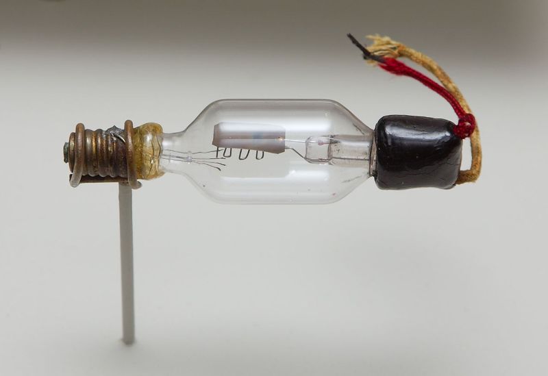
In 1905, using this discovery, John Fleming created the first electron tube — "a device for converting alternating current into direct current." This date is considered the beginning of the birth of all electronics (see — What are the differences between electronics and electrical engineering). The period from 1935 to 1950is considered the golden age of all tube circuits.
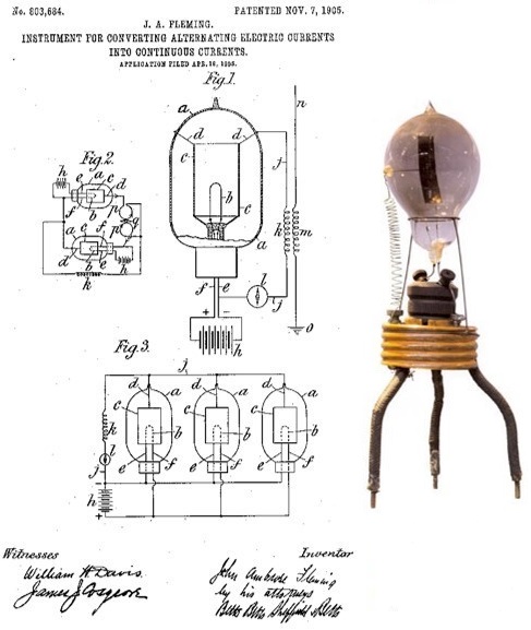
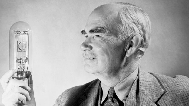
Patent of John Fleming
Vacuum tubes played a very important role in the development of radio engineering and electronics. With the help of a vacuum tube it turned out to be possible to generate continuous oscillations, necessary for radiotelephony and television. It became possible to amplify the received radio signals, thanks to which the reception of very distant stations became available.
In addition, the electronic lamp turned out to be the most perfect and reliable modulator, that is, a device for changing the amplitude or phase of high-frequency oscillations to a low frequency, which is necessary for radio telephony and television.
Isolation of audio frequency oscillations in the receiver (detection) is also most successfully accomplished using an electron tube. The operation of the vacuum tube as an AC rectifier for a long time provided power for radio transmitting and receiving devices. In addition to all this, vacuum tubes were widely used in electrical engineering (voltmeters, frequency counters, oscilloscopes, etc.), as well as the first computers.
The appearance in the second decade of the 20th century of commercially available technically suitable electron tubes gave radio engineering a powerful impetus that transformed all radio engineering equipment and made it possible to solve a number of problems inaccessible to damped oscillation radio engineering.
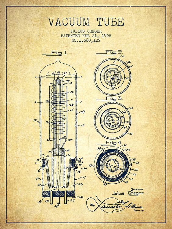
Vacuum tube patent 1928
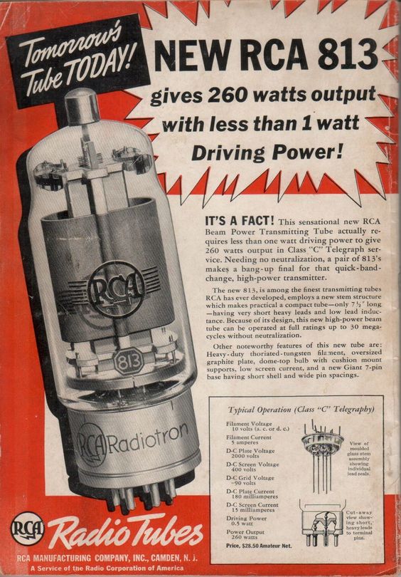
Advertisement for lamps in radio engineering magazine 1938
Disadvantages of vacuum tubes: large size, bulkiness, low reliability of devices built on a large number of lamps (thousands of lamps were used in the first computers), the need for additional energy to heat the cathode, high heat release, often requiring additional cooling.
The principle of operation and the device of electron tubes
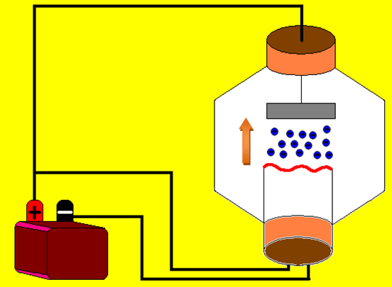
The vacuum tube uses the process of thermionic emission—the emission of electrons from heated metal in an evacuated cylinder. The residual gas pressure is so negligible that the discharge in the lamp can practically be considered purely electronic, since the positive ion current is vanishingly small compared to the electron current.
Let's look at the device and the principle of operation of a vacuum tube using the example of an electronic rectifier (kenotron). These rectifiers, using an electronic current in a vacuum, have the highest correction factor.
The kenotron consists of a glass or metal balloon in which a high vacuum (about 10-6 mmHg Art.) is created. An electron source (filament) is placed inside the balloon, which serves as a cathode and is heated by a current from an auxiliary source: it is surrounded by a large-area electrode (cylindrical or flat), which is the anode.
Electrons emitted from the cathode falling into the field between the anode and the cathode are transferred to the anode if its potential is higher. If the cathode potential is higher, then the kenotron does not transmit current. The current-voltage characteristic of the kenotron is almost perfect.
High voltage kenotrons were used in power circuits for radio transmitters.In laboratory and radio amateur practice, small kenotron rectifiers were widely used, allowing to obtain 50 — 150 mA rectified current at 250 — 500 V. alternating currentremoved from the auxiliary winding of the transformer supplying the anodes.
To simplify the installation of rectifiers (usually full-wave rectifiers), double-anode kenotrons were used, containing two separate anodes in a common cylinder with a common cathode. The relatively small interelectrode capacitance of the kenotron with a suitable design (in this case it is called a diode) and the nonlinearity of its characteristics made it possible to use it for various radio engineering needs: detection, automatic settings of the receiver mode and other purposes.
Two cathode structures were used in vacuum tubes. Cathodic direct (direct) filaments are made in the form of an incandescent wire or strip heated by current from a battery or transformer. Indirectly heated (heated) cathodes are more complex.
Tungsten filament - the heater is insulated with a heat-resistant layer of ceramics or aluminum oxides and is placed inside a nickel cylinder covered by an oxide layer on the outside. The cylinder is heated by heat exchange with the heater.
Due to the thermal inertia of the cylinder, its temperature, even when supplied with alternating current, is practically constant. The oxide layer that gives noticeable emissions at low temperatures is the cathode.
The disadvantage of the oxide cathode is the instability of its operation when it is heated or overheated.The latter can occur when the anode current is too high (close to saturation), because due to the high resistance the cathode overheats, in this case the oxide layer loses emission and may even collapse.
The great advantage of the heated cathode is the absence of a voltage drop across it (due to the filament current during direct heating) and the ability to power the heaters of several lamps from a common source with complete independence of the potentials of their cathodes.
The special shapes of the heaters are related to the desire to reduce the harmful magnetic field of the glow current, which creates a «background» in the radio receiver speaker when the heater is supplied with alternating current.
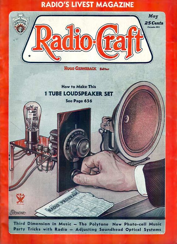
Cover of "Radio-craft" magazine, 1934
Lamps with two electrodes
Two electrode lamps were used for alternating current rectification (kenotrons). Similar lamps used in radio frequency detection are called diodes.
Three-electrode lamps
A year after the appearance of a technically suitable lamp with two electrodes, a third electrode was introduced into it - a grid made in the form of a spiral, located between the cathode and the anode. The resulting three-electrode lamp (triode) has acquired a number of new valuable properties and is widely used. Such a lamp can now work as an amplifier. In 1913, with his help, the first autogenerator was created.
Inventor of the triode Lee de Forest (added a control grid to the electron tube)
The Lee Forrest Triode, 1906.
In a diode, the anode current is a function only of the anode voltage. In a triode, the grid voltage also controls the anode current. In radio circuits, triodes (and multi-electrode tubes) are usually used with an alternating mains voltage called the «control voltage».
Multi-electrode lamps
Multi-electrode tubes are designed to increase the gain and reduce the input capacitance of the tube. The additional grid anyway protects the anode from other electrodes, which is why it is called a shielding (screen) grid. The capacitance between the anode and the control grid in shielded lamps is reduced to hundredths of a picofarad.
In a shielded lamp, changes in the anode voltage affect the anode current much less than in a triode, therefore the gain and internal resistance of the lamp increase sharply, while the slope differs from the triode slope relatively little.
But the operation of a shielded lamp is complicated by the so-called dynatron effect: at sufficiently high speeds, electrons reaching the anode cause a secondary emission of electrons from its surface.
To eliminate it, another network called a protective (antidynatron) network is introduced between the grid and the anode. It connects to the cathode (sometimes inside the lamp). Being at zero potential, this grid slows down the secondary electrons without significantly affecting the movement of the primary electron flow. This eliminates the dip in the anode current characteristic.
Such five-electrode lamps — pentodes — have become widespread, because depending on the design and mode of operation, they can acquire different properties.
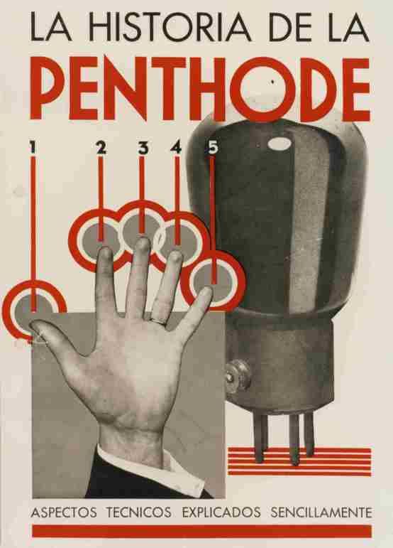
Antique advertisement for Philips pentode
High-frequency pentodes have an internal resistance of the order of a megohm, a slope of several milliamps per volt, and a gain of several thousand. Low-frequency output pentodes are characterized by significantly lower internal resistance (tens of kilo-ohms) with a steepness of the same order.
In so-called beam lamps, the dynatron effect is eliminated not by the third grid, but by the concentration of the electron beam between the second grid and the anode. It is achieved by symmetrically arranging the turns of the two grids and the distance of the anode from them.
Electrons leave the grids in concentrated «flat beams». Beam divergence is further limited by zero-potential protective plates. A concentrated electron beam creates a space charge on the anode. A minimum potential is formed near the anode, which is sufficient to slow down the secondary electrons.
In some lamps, the control grid is made in the form of a spiral with a variable pitch. Since the grating density determines the gain and slope of the characteristic, in this lamp the slope turns out to be variable.
At slightly negative network potentials the entire network works, the steepness turns out to be significant. But if the grid potential is strongly negative, then the dense part of the grid will practically not allow the passage of electrons, and the operation of the lamp will be determined by the properties of the sparsely wound part of the spiral, therefore, the gain and steepness are significantly reduced.
Five grid lamps are used for frequency conversion. Two of the networks are control networks — they are supplied with voltages of different frequencies, the other three networks perform auxiliary functions.
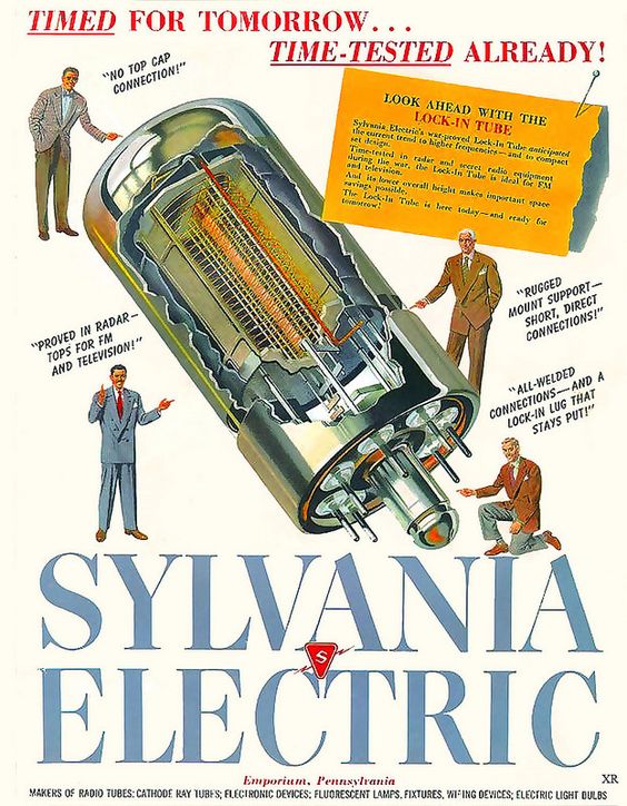
A 1947 magazine ad for electronic vacuum tubes.
Decorating and marking lamps
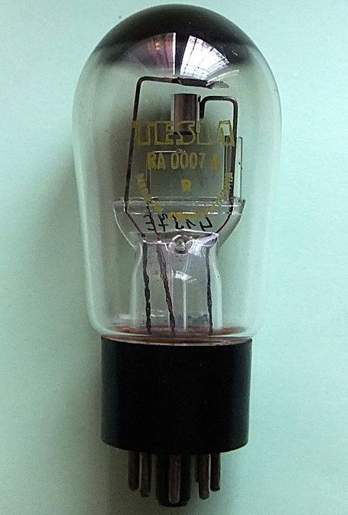
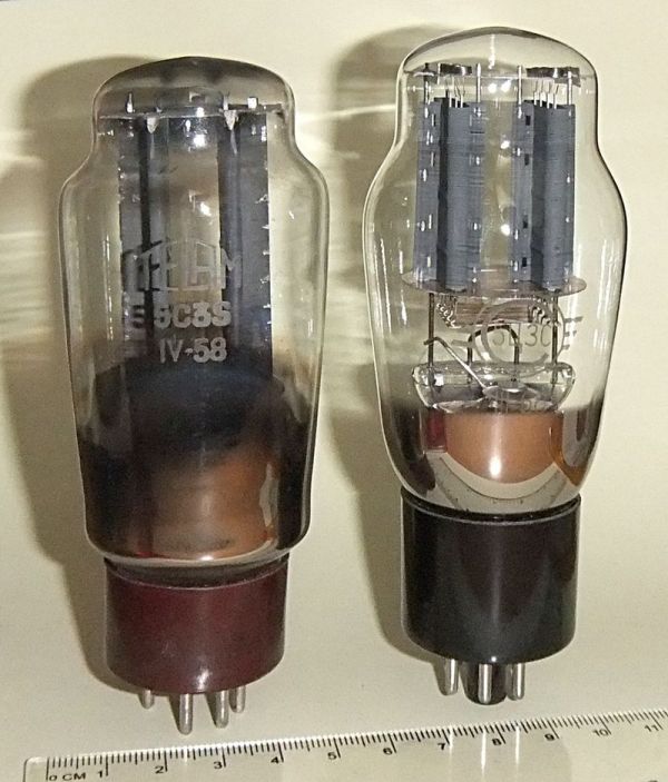
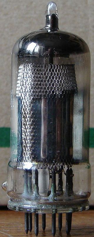
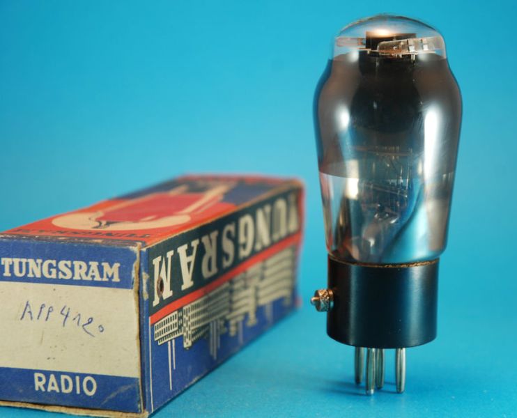
There were a huge number of different types of vacuum tubes. Along with glass bulb lamps, metal or metallized glass bulb lamps are widely used. It protects the lamp from external fields and increases its mechanical strength.
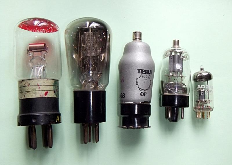
The electrodes (or most of them) lead to the pins on the base of the lamp. The most common eight-pin base.
Small "finger", "acorn" type lamps and miniature lamps with a balloon diameter of 4-10 mm (instead of the usual diameter of 40-60 mm) do not have a base: the electrode wires are made through the base of the balloon - this reduces the capacitance between the inputs. Small electrodes also have low capacitance, so such lamps can operate at higher frequencies than conventional ones: up to frequencies of the order of 500 MHz.
Beacon lamps were used for operation at higher frequencies (up to 5000 MHz). They differ in anode and grid design. The disk-shaped grid is located in the flat base of the cylinder, soldered into the glass (anode) at a distance of tenths of a millimeter. In powerful lamps, the balloons are made of special ceramics (ceramic lamps). Other lamps are available for very high frequencies.
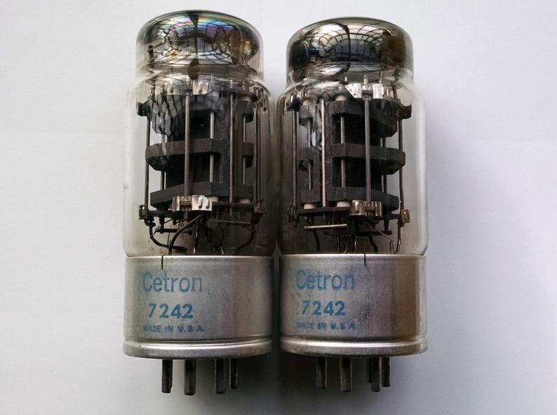
In electron tubes of very high power it was necessary to increase the area of the anode and even resort to forced air or water cooling.
The marking and printing of the lamps are very diverse. Also, marking systems have changed several times. In the USSR, a designation of four elements was adopted:
1. A number indicating the filament voltage, rounded to the nearest volt (the most common voltages are 1.2, 2.0, and 6.3 V).
2. A letter indicating the type of lamp. So, diodes are designated by the letter D, triodes C, pentodes with a short characteristic Zh, with a length K, output pentodes P, double triodes H, kenotrons Ts.
3. A number indicating the serial number of the factory design.
4. The letter that characterizes the design of the lamp.So now metal lamps do not have the last designation at all, glass lamps are indicated by the letter C, finger P, acorns F, miniature B.
Detailed information on the markings, pins and dimensions of the lamps is best sought in specialized literature from the 40s to the 60s. XX century.
The use of lamps in our time
In the 1970s, all vacuum tubes were replaced by semiconductor devices: diodes, transistors, thyristors, etc. In some areas, vacuum tubes are still used, for example in microwave ovens. magnetrons, and kenotrons are used for rectification and fast switching of high voltage (tens and hundreds of kilovolts) in electrical substations for the transmission of electricity by direct current.
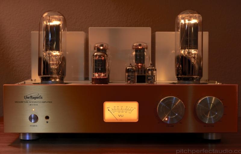
There are a large number of self-made people, the so-called «tube sound», which these days constructs amateur sound devices on electronic vacuum tubes.