Infrared thermography and thermal imaging
Measuring the surface temperature by recording the parameters of the heat radiation emitted by it using electro-optical devices is called infrared thermography. As you can guess, in this case the heat is transferred from the examined surface — to the measuring device, in the form infrared electromagnetic waves.
Modern electro-optical devices for infrared thermography can measure the flow of infrared radiation and, based on the data obtained, calculate the temperature of the surface with which the measuring equipment interacts.
Of course, a person is able to sense infrared radiation and can even sense temperature changes within hundredths of a degree with nerve endings on the surface of the skin. However, with such high sensitivity, the human body is not adapted to detect relatively high temperatures by touch without harming health. At best, this is fraught with burn injuries.
And even if man's sensitivity to temperature turns out to be as high as that of animals capable of detecting prey by heat in total darkness, still sooner or later he will need a more sensitive instrument that can work in more a wider temperature range than natural physiology allows...
After all, such a tool was developed. At first these were mechanical devices, and later hypersensitive electronic ones. Today, these devices seem to be the usual attributes when thermal control needs to be performed to solve any of the myriad technical problems.
The very word «infrared», or abbreviated «IR», denotes the position of heat waves «behind the red», according to their location in the scale of the widest spectrum of electromagnetic radiation. As for the word "thermography", it includes "thermo" - temperature and "graphic" - image - temperature image.
The origins of infrared thermography
The foundation of this line of research was laid by the German astronomer William Herschel, who conducted research with the spectra of sunlight in 1800. By transmitting sunlight through a prism, Herschel placed a sensitive mercury thermometer in areas of different colors on which the sunlight falling on the prism, was divided.
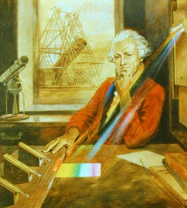
In the course of the experiment, when the thermometer was moved beyond the red line, he found that there was also some invisible, but having a noticeable heating effect, radiation.
The radiation that Herschel observed in his experiment was in that region of the electromagnetic spectrum that was not perceived by human vision as any color.This was the region of "invisible heat radiation", although it was definitely in the spectrum of electromagnetic waves, but below the visible red.
Later, the German physicist Thomas Seebeck would discover thermoelectricity, and in 1829 the Italian physicist Nobili would create a thermopile based on the first known thermocouples, the principle of which would be based on the fact that when the temperature changes between two different metals, the corresponding a potential difference arises at the ends of the circuit composed of these...
Meloni will soon invent the so-called A thermopile (from thermopiles installed in series), and by focusing infrared waves on it in a certain way, will be able to detect a heat source at a distance of 9 meters.
Thermopile — serial connection of thermoelements to obtain greater electrical power or cooling capacity (when operating in thermoelectric or cooling modes, respectively).
Samuel Langley in 1880 discovered a cow in heat at a distance of 300 meters. This will be done using a balometer, which measures the change in electrical resistance that is inextricably linked to a change in temperature.
His father's successor, John Herschel, in 1840 used an evaporograph, with which he obtained the first infrared image in reflected light thanks to the mechanism of evaporation at different speeds of the thinnest film of oil.
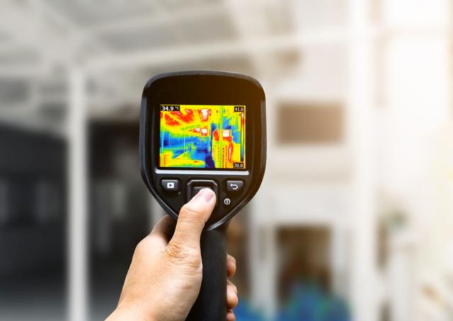
Today, special devices are used for remote acquisition of thermal images — thermal imagers, which allow obtaining information about infrared radiation without contact with the equipment under investigation and immediate visualization. The first thermal imagers were based on photoresistive infrared sensors.
By 1918, American Keys was conducting experiments with photoresistors, where he received signals due to their direct interaction with photons. Thus, a sensitive detector of thermal radiation was created, working on the principle of photoconductivity.
IR thermography in the modern world
During the war years, bulky thermal imagers served mainly military purposes, so the development of thermal imaging technology accelerated after 1940. The Germans found that by cooling the photoresistor receiver, you can improve its characteristics.
After the 1960s, the first portable thermal imagers appeared, with the help of which they carry out diagnostics of buildings. They were reliable tools but with poor quality images. In the 1980s, thermal imaging began to be introduced not only in industry, but also in medicine. The thermal cameras were calibrated to give a radiometric image—the temperatures of all points in the image.
The first gas-cooled thermal cameras displayed the image on a black-and-white CRT screen with a cathode ray tube. Even then it was possible to record from the screen onto magnetic tape or photo paper. Cheaper models of thermal cameras are based on vidicon tubes, do not require cooling and are more compact, although thermal imaging is not radiometric.
By the 1990s, matrix infrared receivers became available for civilian use, including arrays of rectangular infrared receivers (sensitive pixels) installed in the focal plane of the device's lens. This was a significant improvement over the first scanning IR receivers.
The quality of the thermal images has improved and the spatial resolution has increased. Average modern matrix thermal imagers have receivers with a resolution of up to 640 * 480 — 307,200 micro-IR receivers. Professional devices can have a higher resolution — over 1000 * 1000.
IR matrix technology evolved in the 2000s. Thermal imagers have appeared with a long wavelength operating range — sensing wavelengths from 8 to 15 microns and medium wavelengths — designed for wavelengths from 2.5 to 6 microns. The best models of thermal imagers are completely radiometric, have an image overlay function and a sensitivity of 0.05 degrees or less. Over the past 10 years, the price for them has decreased more than 10 times, and the quality has improved. All modern models can interact with a computer, analyze the data itself and present convenient reports in any suitable format.
Heat insulators
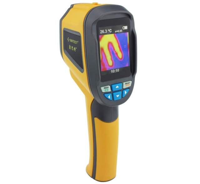
The thermal isolator includes several standard parts: lens, display, infrared receiver, electronics, measurement controls, storage device. The appearance of the various parts may differ depending on the model. The thermal imager works as follows. The infrared radiation is focused by the optics onto the receiver.
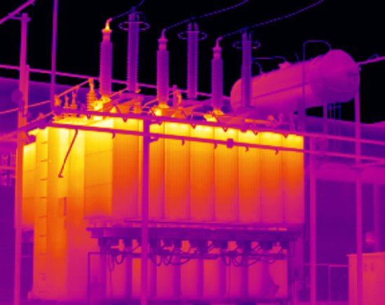
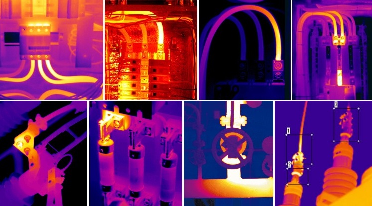
The receiver generates a signal in the form of a voltage or variable resistance. This signal is fed to the electronics, which forms an image — a thermogram — on the screen.Different colors on the screen correspond to different parts of the infrared spectrum (each shade corresponds to its own temperature), depending on the nature of the heat distribution on the surface of the object examined by the thermal imager.
The display is usually small, has high brightness and contrast, which allows you to see the thermogram in different lighting conditions. In addition to the image, the display usually shows additional information: battery charge level, date and time, temperature, color scale.
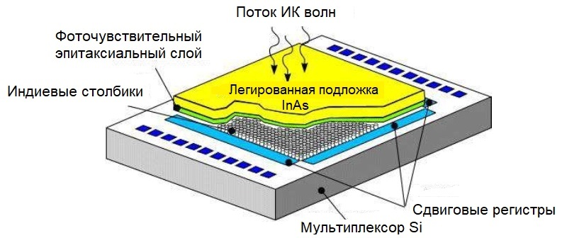
The IR receiver is made of a semiconductor material that generates an electrical signal under the influence of infrared rays falling on it. The signal is processed by electronics that form an image on the display.
For control, there are buttons that allow you to change the range of measured temperatures, adjust the color palette, reflectivity and background emission, as well as save images and reports.
Digital image and report files are usually saved to a memory card. Some thermal imagers have the function of recording voice and even video in the visual spectrum. All digital data saved while operating the thermal imaging camera can be viewed on a computer and analyzed using the software supplied with the thermal imaging camera.
See also:Non-contact temperature measurement during operation of electrical equipment