Current and voltage measuring transformers — projects, technical characteristics
 Instrument current and voltage transformers are designed to reduce primary currents and voltages to values that are most convenient for connecting measuring instruments, protective relays and automation devices. The use of measuring transformers ensures the safety of workers, since the high and low voltage circuits are separated, and also allows the unification of the design of devices and relays.
Current transformers are classified:
-
by design — sleeve, built-in, through, support, rail, detachable;
-
type of installation — external, for closed and complete distribution devices;
-
the number of transformation stages — single-stage and cascade;
-
transformation coefficients — with one or more values;
-
the number and purpose of the secondary windings.
Letter designations:
-
T — current transformer;
-
F — with porcelain insulation;
-
H — external mounting;
-
K — cascade, with capacitor insulation or coil;
-
P — checkpoint;
-
O — single-turn rod;
-
Ш — single-turn bus;
-
B-air-insulated, built-in or water-cooled;
-
L — with cast insulation;
-
M-oil-filled, upgraded or small in size;
-
P — for relay protection;
-
D — for differential protection;
-
H — for protection against earth faults.
Technical characteristics of current transformers
Rated primary and secondary current of current transformers
Current transformers are characterized by a rated primary current Inom1 (the standard scale of rated primary currents contains values from 1 to 40,000 A) and a rated secondary current Inom2, which is taken as 5 or 1 A. The ratio of the rated primary to the rated secondary current is the coefficient of transformation KTA = Inom1 / Inom2
Current fault current transformers
 Current transformers are characterized by a current error ∆I = (I2K-I1) * 100 / I1 (in percent) and an angular error (in minutes). Depending on the current error, measuring current transformers are divided into five classes of accuracy: 0.2; 0.5; 1; 3; 10. The name of the accuracy class corresponds to the current limit error of the current transformer at a primary current equal to 1-1.2 nominal. For laboratory measurements, current transformers with an accuracy class of 0.2 are intended, for connecting electricity meters - current transformers of class 0.5, for connecting panel measuring devices - classes 1 and 3.
Load current transformers
The current transformer load is the impedance of the external circuit Z2, expressed in ohms. The resistances r2 and x2 represent the resistance of devices, wires and contacts. The transformer load can also be characterized by the apparent power S2 V * A.The rated load of the current transformer Z2nom is understood as a load at which errors do not exceed the limits established for transformers of this accuracy class. The value of Z2nom is given in the catalogs.
Electrodynamic resistance of current transformers
The electrodynamic resistance of current transformers is characterized by the nominal current of the dynamic resistance Im.din.or by the ratio kdin = The thermal resistance is determined by the nominal thermal current It or by the ratio kt = It / I1nom and the allowable time of the withstand current tt.
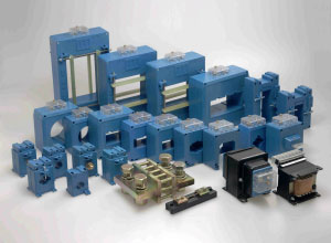
Current transformer designs
By construction, current transformers are distinguished by winding, single-turn (type TPOL), multi-turn with resin casting (type TPL and TLM). The TLM type transformer is intended for distribution devices and is structurally combined with one of the plug connectors of the primary circuit of the cell.
For high currents, TShL and TPSL type transformers are used, where the busbar plays the role of the primary winding. The electrodynamic resistance of such current transformers is determined by the busbar resistance.
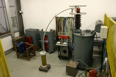
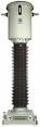
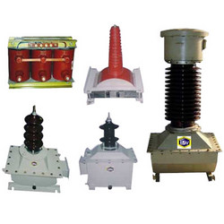
For outdoor switchgear, TFN-type transformers are manufactured in porcelain housing with paper-oil insulation and cascade type TRN. There are special designs for relay protection. Built-in current transformers are installed at the terminals of oil tank switches and power transformers with a voltage of 35 kV and above. All other things being equal, their error is greater than that of free-standing transformers.
Technical characteristics of instrument voltage transformers
Rated primary and secondary voltage of instrument voltage transformers
Voltage transformers are characterized by the nominal values of the primary voltage, the secondary voltage (usually 100 V), transformation factor K = U1nom / U2nom. Depending on the error, the following accuracy classes of voltage transformers are distinguished: 0.2; 0.5; 1:3.
Voltage transformer load
The secondary load of the voltage transformer is the power of the external secondary circuit. The nominal secondary load is understood as the largest load at which the error does not exceed the permissible limits established for transformers of a given accuracy class.
Projects for voltage transformers
In installations with voltages up to 18 kV, three-phase and single-phase transformers, at higher voltages — only single-phase. At voltages up to 20 kV, there are a large number of types of voltage transformers: dry (NOS), oil (NOM, ZNOM, NTMI, NTMK), resin cast (ZNOL). It is necessary to distinguish single-phase two-winding transformers NOM from single-phase three-winding transformers ZNOM. Transformers of types ZNOM -15, -20 -24 and ZNOL -06 are installed in complete buses of powerful generators. In installations with a voltage of 110 kV and above, voltage transformers of the cascade type NKF and capacitive voltage dividers NDE are used.
Wiring diagrams of a voltage transformer
Depending on the purpose, different voltage transformer switching schemes can be used. Two single-phase voltage transformers connected in incomplete delta can measure two line voltages.A similar scheme is recommended for connecting meters and wattmeters. For measuring line and phase voltage three single-phase transformers (ZNOM, ZNOL) connected according to the «star-star» scheme or three-phase type NTMI can be used. Single-phase three-winding transformers of the ZNOM and NKF types are also connected in a three-phase group.
It is not recommended to connect measuring devices to three-phase voltage transformers, as they usually have an asymmetric magnetic system and increased error. For this purpose, it is recommended to install a group of two single-phase transformers connected in incomplete delta.
Voltage transformers are selected according to the conditions Uset ≤U1nom, S2≤ S2nom in the intended accuracy class. For S2nom, take the power of the three phases of single-phase voltage transformers connected in a star circuit and twice the power of a single-phase transformer connected in an incomplete delta circuit.