RPL electromagnetic relays — device, principle of operation, technical characteristics
Electromagnetic intermediate relays
 Electromagnetic relays Are electromechanical relays whose operation is based on the effect of a magnetic field of a stationary current-carrying coil on a moving ferromagnetic element called an armature. Electromagnetic relays are divided into their own electromagnetic (neutral), which react only to the value of the current in the coil, and polarized, the operation of which is determined by both the value of the current and its polarity.
Electromagnetic relays for industrial automatic devices occupy an intermediate position between high-current switching devices (contactors, magnetic starters etc.) and low current equipment. The most common type of these relays are electric drive control relays (control relays), and among them are intermediate relays.
Control relays are characterized by intermittent and intermittent-continuous modes of operation with the number of operations up to 3600 per hour with high mechanical and switching durability (the latter is up to switching cycles).
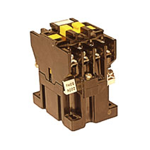
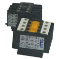
RPL electromagnetic relays
 An example of intermediate relays is RPL electromagnetic relays… RPL relays are intended for use as components in stationary installations, mainly in electrical circuits for controlling voltages up to 440V DC and up to 660 V AC with a frequency of 50 and 60 Hz. RPL electromagnetic relays are suitable for operation in control systems using microprocessor technology when the closing coil is surrounded by a limiter limiter or with thyristor control.
If necessary, one of the prefixes PKL and PVL can be installed on the intermediate relay RPL.
Rated current of the contacts of the RPL relay — 16A Allowable current in industrial mode — 10 A. Relays of two modifications are produced: RPL -1 — with alternating current supply to the input circuit and RPL -2 — with DC supply. Structurally, they differ from each other only in the magnetic system.
The device and principle of operation of electromagnetic relays RPL
When voltage is applied to the coil 5, a magnetic flux occurs in the magnetic circuit, creating an electromagnetic force, which, overcoming the opposition of the return spring 3, moves the armature 4 from the stops 9 in such a way as to reduce the working clearances and the magnetic system.
With the anchor through the rod 6 and the contact spring 1 located on the guide 10, the contact bridge 8 is connected to two contact parts 2. At a certain position of the anchor, the latter are in contact with the stationary contact parts 2'2'.
With further movement of the armature to its final position, an increase in the contact voltage occurs due to the compression of the contact spring 1.At the same time, the contact bridge 8 moves up with a distance because the guide 10 is not perpendicular to the bridge. As a result of contact parts slipping, their surfaces are self-cleaning during relay operation. In the final position of the anchor, its vibration is eliminated by the action of short-circuited turns 7.
After removing the input signal, the magnetic flux in the magnetic circuit decreases to the residual value. At a certain value of the flow, greater than the residual, the force developed by the springs 1 and 3, deformed during operation, becomes greater than the electromagnetic force. The armature returns to its original position, the contacts open. In order to reduce the residual flow to a value where the "sticking" of the armature is excluded, in the considered design, the gap is assumed to be large. Therefore, for the gap > 0.
Technical characteristics of electromagnetic relay RPL
Rated insulation voltage, V
660
Rated current of the main circuit, A
16
Nominal voltage of the pickup coil, V
24, 36, 40, 110, 127, 220, 230, 240, 380, 400, 415, 440, 500 and 600 V frequency 50 Hz
36, 110, 220, 380 and 440 V 60Hz
Power consumed by the starter coil (operating / starting, V, A)
8±1.4/68±8
Rated operating current, A (category of use AC — 11 at voltages 380, 500, 660 V)
0.78; 0.5; 0.3
Wear resistance (mechanical / switching) for wear resistance design A, B millions of cycles
20/3; 20/1.6
Maximum switching frequency (without load / with load), switches per hour
3600/1200
Overall / installation dimensions, mm (screw fastening)
67x44x74.5 / 50x35
Overall / installation dimensions, mm (installation on standard rails)
69.5x44x79.5 / 35
Weight, kg, no more (screw / standard rail)
0.32/0.35
The structure of the conventional designation of an electromagnetic relay RPL
PKL series contact attachments
 Designed to increase the number of auxiliary contacts of an RPL relay or PML starter. Each of the starters can be equipped with a 2- or 4-pole attachment with a different set of breaks and contacts.
The contact devices are mechanically connected to the starters and fixed with a lock. The mounting method ensures a firm and reliable connection between the contact attachment and the starter.
PKL contact attachments are produced with IP00 and IP20 degrees of protection, in two versions in terms of wear resistance: A — 3.0 million cycles; B — 1.6 million cycles.
PKL attachment selection table
Type designation
Number of contacts
Rated current of the contacts, A
Closing
Unlocking
PKL — 20 (M)
2
—
16
PKL — 11 (M)
1
1
16
PKL — 40 (M)
4
—
16
PKL — 04 (M)
—
4
16
PKL — 22 (M)
2
2
16
Connect to attachments to create a PVL time delay
Time delay prefixes are used as components in stationary installations, mainly in control circuits of electric drives at voltages up to 440V DC and up to 660V AC with a frequency of 50 and 60Hz. The pneumatic fixture is designed to create a time delay when the RPL relay or PML starter is turned on or off.
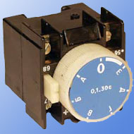
The attachments are mechanically connected to the starters and are fixed with a lock. The mounting method ensures a firm and reliable connection between the time delay attachment and the starter. PVL pneumatic devices are produced with IP00 and IP20 degrees of protection, in two wear resistance versions: A — 3.0 million cycles; B — 1.6 million cycles.
PVL table for selection of pneumatic attachments
Type designation
Number of contacts
Time delay range, s
A kind of time delay
Rated current of the contacts, A
Closing
Unlocking
PVL-11 (M)
1
1
0.1-30
Power-on delay
10
PVL-12 (M)
1
1
10-180
10
PVL-13 (M)
1
1
0.1-15
10
PVL-14 (M)
1
1
10-100
10
PVL-21 (M)
1
1
0.1-30
Shutdown delay
10
PVL-22 (M)
1
1
10-180
10
PVL-23 (M)
1
1
0.1-15
10
PVL-24 (M)
1
1
10-100
10