Time relay with electromagnetic and mechanical delay
When working with protection and automation circuits, it is often necessary to create a time delay between the operation of two or more devices. When automating technological processes, it may be necessary to carry out operations in a certain time sequence.
To create a time delay, devices called time relays are used.
Time relay requirements
The general requirements for time relays are:
a) delay stability, regardless of fluctuations in supply voltage, frequency, ambient temperature and other factors;
b) low energy consumption, weight and dimensions;
c) sufficient power of the contact system.
 The time relay returns to its original position, as a rule, when it is turned off. Therefore, there are no special requirements for the rate of return and it can be very low.
Depending on the purpose of the relay, specific requirements are imposed on them.
Relays are required for automatic drive control schemes with high starting frequency per hour time with high mechanical resistance to wear. The required time delays are in the range of 0.25 — 10 s. These relays are not subject to high requirements regarding the accuracy of operation. The response time distribution can be up to 10%. Relay time must work in the conditions of production workshops, with vibrations and shaking.
Time relays for power system protection must have high time delay accuracy. These relays operate relatively infrequently, so there are no special endurance requirements. The delays of such relays are 0.1 — 20 s.
Time relay with electromagnetic time delay
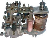
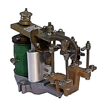
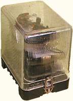
The REV-800 Type Electromagnetic Time Delay Relay Design. The magnetic circuit of the relay consists of a magnetic circuit 1, an armature 2 and a non-magnetic spacer 3. The magnetic circuit is fixed on a plate 4 using an aluminum base 5. The same base is used to fix the contact system 6.
A short circuit in the form of a flattened sleeve 8 is mounted on the yoke of a rectangular section of the magnetic circuit. The magnetic coil 7 is mounted on a cylindrical core. The armature rotates relative to rod 1 of the prism. The force developed by the spring 9 is changed using a castellated nut 10, which is fixed after adjustment using a pin. The magnetic circuit of the relay is made of EAA steel. The coil core has a circular cross-section, which makes it possible to use a cylindrical coil, which is convenient to manufacture.Rod 1 has a cross-section of an elongated rectangle, which increases the length of the contact line between the armature and the end of the yoke and increases the mechanical durability of the relay.
To obtain a long release time, it is necessary to have a high magnetic conductivity of the working and parasitic gaps in the closed state of the magnetic system. For this purpose, the ends of the yoke and the core and the adjacent surface of the armature are carefully polished.
 The cast aluminum base creates an additional short circuit turn, increasing the time delay (in the equivalent circuit, all the short circuits of the windings are replaced by one turn of common electrical conductivity).
In real magnetic materials, after the magnetizing coil is turned off, the flux drops to Fost, which is determined by the properties of the magnetic circuit material and the geometrical dimensions of the magnetic circuit. The lower the coercive force of the magnetic material for a given size of the magnetic circuit, the lower the value of the residual induction and, accordingly, the residual flux. This increases the longest delay time that can be obtained from the relay. Using EAA steel makes it possible to increase the delay time of the relay.
To obtain a long delay, it is desirable to have a high magnetic permeability in the unsaturated part of the magnetization curve. EAA steel also meets this requirement.
The time delay, other things being equal, is determined by the initial flux Fo of Eq. This flux is determined by the magnetization curve of the magnetic system in the closed state.Since the voltage and current in the coil are proportional to each other, the dependence Ф (U) repeats, only on a different scale, the dependence Ф (Iw). If the system at rated voltage is not saturated, then the flux Fo will depend largely on the supply voltage. In this case, the time delay will also depend on the voltage applied to the coil.
 In drive circuits, a voltage below the rated voltage is often applied to the relay coil for a time while the relay will have reduced time delays. To make the relay delay independent of the supply voltage, the magnetic circuit is heavily saturated. In some types of time relays, a voltage drop of 50% does not cause a noticeable change in the delay time.
In automation circuits, the voltage to the supply coil of the timing relay can be provided for a short time. In order for the stability of the release time to be stable, it is necessary that the duration of applying voltage to the supply coil is sufficient to reach a stable current. This time is called the relay preparation time or charging time. If the duration of the voltage supply is shorter than the preparation time, then the delay is reduced.
The relay delay is greatly affected by the short circuit temperature. On average, we can assume that a 10°C change in temperature results in a 4% change in retention time. The temperature dependence of the delay is one of the main disadvantages of this relay.
REV811 … REV818 relays provide a time delay from 0.25 to 5.5 s. Manufactured with 12, 24, 48, 110 and 220 V DC coils.
Time relay switching diagrams
 The response time of the relay when voltage is applied is very short, from pm s. startup is much less than the steady-state value. Thus, the capabilities of an electromagnetic lift delay relay are very limited. If it is necessary to have long delays when closing the control contacts, then it is recommended to use a circuit with an intermediate relay RP. The coil of the PB time relay is energized, all the time being energized through the opening contact of the RP relay. .When voltage is applied to the RP coil, the latter opens its contact and de-energizes the PB relay. The PB armature disappears, creating the necessary time delay. The PB relay in this circuit must be short-circuited.
In some circuits, the timing relay may not be shorted. The role of this turn is played by the short-circuited magnetizing coil itself. The RV coil is fed through a Radd resistor. The voltage across RV must be sufficient to achieve saturation flux in the closed state of the magnetic circuit. When the control contact K closes, the relay coil is short-circuited, which provides a slow decay of the flux in the magnetic circuit. The absence of a short circuit allows the entire window of the magnetic system to be occupied by the magnetizing coil and create a large margin in ppm.s. In this case, the time delay does not decrease even in the case where the coil supply voltage is 0.5 Un. This scheme is widely used in electric drives. The relay is connected in parallel with the starting resistor stage in the armature circuit.When this stage is closed, the coil of the time relay closes and with a delay this relay turns on the contactor, bypassing the next stage of the starting resistor.
Schemes for switching on a time relay with a delay solenoid
The use of a solid state valve also allows the use of a relay without a short circuit. When the supply coil is switched on for a time relay, the current through the valve is practically zero because it is switched on in the non-conducting direction. When the contact K is closed, the flux in the magnetic circuit decreases while an emf appears at the coil terminals. with polarity. In this case, a current flows through the valve, which is determined by this EMF, the active resistance of the coil and the valve and inductance of the coil.
So that the direct resistance of the valve does not lead to a decrease in the time delay (the active resistance of the short circuit increases), this resistance must be one to two orders of magnitude lower than the resistance of the magnetizing coil of the relay.
For any circuits, the magnetizing coil of the relay must be powered from either a DC source or an AC source using a solid state valve bridge circuit.
Time relay with mechanical delay
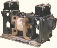
Time relay with pneumatic delay and latching mechanism. In such relays, a DC or AC electromagnet acts on a contact system connected to a retarding device in the form of a pneumatic shock absorber or in the form of a clock (armature) mechanism. The delay is changed by adjusting the retarder.
The great advantage of this type of time relay is the ability to create an AC and DC relay.The operation of the relay practically does not depend on the value of the supply voltage, supply frequency, temperature.
RVP pneumatic time switch used in automatic circuits for controlling the drive of metal cutting machines and other mechanisms. When electromagnet 1 is actuated, block 2 is released, which under the action of spring 3 falls and acts on microswitch 4. Block 2 is connected to diaphragm 5. The speed of movement of the block is determined by the section of the hole through which air is sucked into the upper cavity to the moderator. The delay is adjusted by the needle 6, which changes the section of the suction hole.
 The pneumatic delay time relay makes it very easy to adjust the delay.
The operation of a time relay with a retarder in the form of an armature mechanism proceeds in the following order. When voltage is applied to the electromagnet, the armature starts a spring, under the action of which the relay mechanism is set in motion. The contacts of the relay are connected to the armature mechanism and start moving only after the armature mechanism counts down a certain time.
The RVP time relay also has non-regulated, momentary contacts that are connected to the armature of the solenoid. Time relays reliably work at voltages up to 0.85 Un.
Engine timing relay
To create a time delay of 20-30 minutes, motor time relays are used.
The principle of operation of the engine timing relay RVT-1200
When the time relay is actuated, the voltage is applied simultaneously to the solenoid 1 and the motor 2.In this case, the motor rotates discs 5 with cams 6 acting on the contact system 7 through the clutch 3,4 and gear 8 and the relay delay is rotated by changing the initial position of the disc 5.
The relay allows you to set different time delays in five completely independent circuits. Time relay output contacts have a long-term permissible current of 10 A.