Power controllers: purpose, device, technical characteristics
The controller is a control device designed to start, stop, regulate the speed of rotation and reverse electric motors. Contact controllers are included directly in the supply chain of electric motors with a voltage of no more than 600 V.
According to the location of the contact parts, controllers with sliding contacts and cam type are distinguished. Controllers for sliding contacts, in turn, are divided into drum and flat (the latter are rarely used).
The controller shaft can be rotated manually or by a drive mechanism or a separate electric motor. The fixed contacts (fingers) are located in the apparatus housing around the shaft with contacts and are isolated from it. Controllers are produced only in a secure version. Lever spring mechanisms are used to fix the shift positions.
The preset switching program of the controller is realized by the corresponding arrangement of the movable contacts (segments).To improve switching conditions, DC controllers are supplied with magnetic backfill. The number of switching positions is usually from 1 to 8 (sometimes up to 12-20), the value of the switched current does not exceed 200 A.
Controllers can operate in intermittent mode with a relative duty cycle (25-60%) or in continuous mode. Permissible switching frequency drum-type controllers do not exceed 300, and cam-type controllers - up to 600 switches per hour. The controllers have become the most common in the electric drive of lifting and transport machines and mechanisms.
Power controllers are complete devices for ensuring the switching on of winding circuits of electric motors according to a predetermined program incorporated in the design of the controller. Simplicity of design, trouble-free operation and small dimensions are the main advantages of power regulators.
With the correct selection and use of power regulators in accordance with their switching capabilities, the controllers are reliable and easy-to-use complete devices for controlling crane electric drives, since in these devices violations of the set program are completely excluded, and the inclusion and dependent operator shutdown ensures 100% device availability. However, the disadvantages of these complete devices include low wear resistance and switching ability, as well as the lack of automated start and stop.
Drum controllers
Figure 1 shows a drum controller pin. A segment holder 2 with a movable contact in the form of a segment is mounted on the shaft 1. The segment holder is isolated from the shaft by insulation 4.The fixed contact 5 is located on an insulated bus 6. When the shaft 1 rotates, the segment 3 moves to the fixed contact 5, thereby closing the circuit. The necessary contact pressure is provided by the spring 7. A large number of contact elements are located along the shaft. A number of such contact elements are mounted on one shaft. The load-bearing segments of adjacent contact elements can be interconnected in the various necessary combinations. A certain sequence of closing different contact elements is provided by different lengths of their segments.
Fig. 1.Drum controller contact element.
Cam controllers
In cam controllers, the opening and closing of contacts is provided by cams mounted on a drum, which are rotated by means of a handwheel handle or pedal and can switch from 2 to 24 electrical circuits. Cam controllers are divided according to the number of circuits included, the type of drive, the contact closure schemes.
In an AC cam controller (Fig. 2), the movable movable contact 1 is able to rotate about the center O2 located on the contact arm 2. The contact arm 2 rotates about the center O1. Contact 1 is closed with a fixed contact 3 and is connected to the output contact using a flexible connection 4. The closing contacts 1,3 and the necessary contact pressure are created by a spring 5 acting on the contact lever through the rod 6. When the contacts open, a cam 7 acts through a roller 5 on the arm of the contact lever. This compresses spring 5 and contacts 1, 3 open. The moment of switching on and off the contacts depends on the profile of the cam pulley 9, which drives the contact elements.Low contact wear makes it possible to increase the number of switch-ons per hour to 600 at a duty cycle of 60%.
The controller includes two sets of contact elements /and //, located on both sides of the cam washer 9, which allows you to sharply reduce the axial length of the device. Both drum and cam controllers have a shaft position locking mechanism.
AC controllers, in order to facilitate arc extinguishing, may not have arc extinguishing devices. Only arc-resistant asbestos-cement partitions 10 are installed in them. DC controllers have an arc extinguishing device similar to that used in contactors.
The controller in question is turned off when the handle is acted upon and this action is transmitted through the cam pulley; it is switched on by the force of the spring 5 with the corresponding position of the handle. Therefore, the contacts can be separated even if they are welded. The disadvantage of the design is the large moment on the shaft due to the closing springs with a significant number of contact elements. It should be noted that other design solutions for the contact drive of the controller are also possible. Fig. 2. Cam controller.
Flat controllers
To smoothly regulate the excitation field of large generators and to start and regulate the speed of rotation of large motors, it is necessary to have a large number of stages. The use of cam controllers is impractical here, since a large number of stages leads to a sharp increase in the dimensions of the apparatus. The number of operations per hour during adjustment and start-up is small (10-12). Therefore, there are no special requirements for the controller in terms of durability.In this case, flat controllers are widely used.
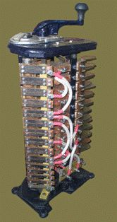
Figure 3 shows a general view of a planar excitation control controller. Fixed contacts 1, in the form of a prism, are fixed on an insulating plate 2, which is the basis of the controller. The arrangement of fixed contacts along the line allows for a large number of steps. With the same controller length, the number of steps can be increased by using a parallel row of contacts offset from the first row. When moved by half a step, the number of steps is doubled.
The movable contact is made in the form of a copper brush. The brush is located in the traverse 3 and is isolated from it. The pressure is generated by a coil spring. The transfer of current from the contact brush 4 to the output terminal is carried out using a current-collecting brush and current-collecting spikes 5. The controller in fig. 3 can simultaneously switch in three independent circuits. The traverse is moved using two screws 6, driven by an auxiliary motor 7. During adjustment, the traverse is moved manually by the handle 8. In the end positions, the traverse acts on the limit switches 9, which stop the engine.
In order to be able to precisely stop the contacts in the desired position, the speed of movement of the contacts is taken small: (5-7) 10-3 m / s, and the motor must be stopped. The flat controller can also have a manual drive.
Fig. 3. Flat controller.
Advantages and disadvantages of different types of controllers
Drum controllers
 Due to the low wear resistance of the contacts, the allowable number of controller starts per hour exceeds 240.In this case, the power of the starting motor must be reduced to 60% of the nominal, which is why such controllers with rare starts are used.
Cam controllers
The controller uses a movable line contact. Due to the rolling of the contacts, the arc that ignites when opening does not affect the contact surface involved in the conduction of the current in the fully on state.
Low contact wear allows to increase the number of starts per hour up to 600 with a duty cycle of 60%.
The design of the controller has the following feature: it is turned off due to the convexity of the cam and turned on due to the force of the spring. Thanks to this, the contacts can be separated even if they are welded.
The disadvantage of this system is the large moment on the shaft created by the closing springs with a significant number of contact elements. Other contact drive designs are also possible. In one of them, the contacts close under the action of the cam and open under the action of the spring, in the other, both the inclusion and the disconnection are carried out by the cam. However, they are rarely used.
Flat controllers
Planar controllers are widely used to modulate the excitation field of large generators and to start and control the speed of large motors. Since it is necessary to have a large number of stages, the use of cam controllers here is impractical, since a large number of stages leads to a sharp increase in the dimensions of the apparatus.
When opening between the movable and fixed contact, a voltage equal to the voltage drop across the steps appears.To prevent arcing, the permissible voltage drop across the steps is taken from 10 V (at a current of 200 A) to 20 V (at a current of 100 A). The permissible number of turns per hour is determined by the wear of the contacts and usually does not exceed 10-12. If the voltage of the steps is 40-50 V, then a special contactor is used that overcomes adjacent contacts during brush movement.
In the event that it is necessary to turn on the circuit at currents of 100 A and more with a switching frequency of 600 and more per hour, a system consisting of a contactor and a controller is used.
The use of power regulators in an electric crane drive
Controllers of the following series are used to control electric motors of crane mechanisms: KKT-60A of alternating current and console controllers DVP15 and UP35 / I. Controllers of this series are produced in protected housings with covers and degree of protection from the external environment 1P44.
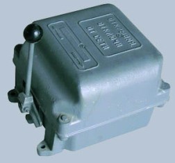
The mechanical endurance of power regulators is (3.2 -5) x 10 million VO cycles. The durability of the switching depends on the strength of the switched current. At rated current it is about 0.5 x 10 million VO cycles and with a current of 50% of rated, you can get wear resistance of 1 x 10 million VO cycles.
The KKT-60A controllers have a rated current of 63 A at a duty cycle of 40%, but their switching capacity is very low, which limits the use of these controllers in difficult switching conditions. The rated voltage of the AC controllers is 38G V, the frequency is 50 Hz .