What you can learn about an electric motor by knowing its catalog data
The asynchronous motor catalogs contain all the data necessary for motor selection.
The catalogs indicate: motor size, rated power for S1 mode (continuous operation), speed at rated power, stator current at rated power, efficiency at rated power, power factor at rated power, starting current frequency, i.e. is. initial starting current to the rated or multiple of the starting power, i.e. the ratio of the total starting power to the rated power, the multiple of the initial starting torque, the multiple of the minimum torque, the dynamic moment of inertia of the rotor.
In addition to these data related to rated or starting mode, the catalogs provide more detailed data on the change in efficiency and power factor as the motor shaft load changes. These data are presented in tabular or graphical form.Using this data, it is also possible to calculate the stator current and slip at different shaft loads.
The catalogs also indicate the necessary dimensions for mounting the motor on site and connecting it to the mains.
The different stages of engine development, distribution, installation, operation and repair require different levels of detail. For most purposes, size-level detail is sufficient. The standard size catalog description of the 4A and AI series motors contains features designated by a maximum of 24 characters.
Examples. 4A160M4UZ — 4A series induction motor, with degree of protection IP44, the bed and shields are cast iron, the height of the axis of rotation is 160 mm, it is made in a bed of medium length M, four-pole, intended for work in a moderate climate, category 3.
4АА56В4СХУ1 — asynchronous motor of the 4A series with IP44 degree of protection, the frame and shields are aluminum, the height of the axis of rotation is 56 mm, it has a long core, four-pole, agricultural modification according to environmental conditions, intended for operation in a moderate climate, category 1 per placement.
The rated power of the motor is the mechanical power of the shaft in the mode of operation for which it is intended by the manufacturer.
Number of nominal powers of electric motors: 0.06; 0.09; 0.12; 0.18; 0.25; 0.37; 0.55; 0.75; 1.1; 1.5; 2.2; 3.7; 5.5; 7.5; eleven; 15; 18.5; 22; thirty; 37; 45; 55; 75; 90; 110; 132; 160; 200; 250; 315; 400 kW.
The maximum permissible engine power may change with changes in operating mode, coolant temperature and altitude.
The motors must maintain their rated power when the mains voltage deviates from the nominal value within ± 5% at the nominal mains frequency and when the mains frequency deviates within ± 2.5% at the nominal voltage. With a simultaneous deviation of the mains voltage and frequency from the nominal values, the motors must maintain their nominal power if the sum of the absolute deviations does not exceed 6% and each of the deviations does not exceed the norm.
Synchronous motor speed
A number of synchronous speeds of rotation of asynchronous motors are set by GOST and at a mains frequency of 50 Hz there are the following values: 500, 600, 750, 1000, 1500 and 3000 rpm.
Dynamic moment of inertia of the electric motor rotor
The measure of the inertia of a body during rotational motion is the moment of inertia, equal to the sum of the products of the masses of all point elements by the square of their distances from the axis of rotation. The moment of inertia of the induction motor rotor is equal to the sum of the moments of inertia of the multistage shaft, core, winding, fan, key, rotating parts of rolling bearings, coil holders and phase rotor thrust washers, etc.
The attachment of electric motors to the object is done by means of feet, flanges or feet and flanges at the same time.
Installation dimensions of asynchronous electric motors with squirrel-cage rotor of lamps (a) and with flange (b)
Leg-mounted electric motors have four basic mounting sizes:
h (H) — distance from the axis of the shaft to the bearing surface of the legs (basic size),
b10 (A) — distance between the axes of the mounting holes,
l10 (B) — distance between the axes of the mounting holes (side view),
l31 (C) — distance from the supporting end of the free end of the shaft to the axis of the nearest mounting holes in the legs.
Electric motors with flanges have four main mounting sizes:
d (M) — diameter of the circle of the centers of the mounting holes,
d25 (N) — diameter of centering of sharpening,
d24 (P) — outer diameter of the flange,
l39 (R) is the distance from the bearing surface of the flange to the bearing surface of the end of the free shaft.
Characteristics of electric motors
Mechanical characteristics and starting properties of the engine
The mechanical characteristic is the dependence of the motor torque on its rotation speed at constant voltage, network frequency and external resistances in the motor winding circuits.
The starting properties are characterized by the values of starting torque Mp, minimum torque Mmin, maximum (critical) moment Mcr, starting current Azp or starting power Pp or their multiples. The dependence of the moment indicated on the nominal slip moment relative mechanical characteristic of the electric motor is called.
Nominal torque of the electric motor, N / m, is determined by the formula
Mnom = 9550 (Rnom / nnom)
where Rnom — nominal power, kW; nnom — nominal speed, rpm.
The variety of mechanical characteristics for different modifications of induction motors is shown in the figure.
Mechanical characteristics of squirrel-cage rotor asynchronous electric motors: 1 — basic radar, 2 — with increased starting torque, 3 — with increased slip.
The mechanical characteristics of a group of engines representing a segment of the series fit into a certain area.The midline of this zone will be called the group mechanical characteristic of the series segment. The width of the group characteristic area does not exceed the moment tolerance field.
Performance characteristics of electric motors
The performance characteristics are the dependences of input power P1, current in the stator winding Az, torque M, efficiency, power factor cos f and slip s on the net power of the motor P2 at a constant voltage at the terminals of the stator winding, the frequency of the network and the external resistances in the motor winding circuits. If such dependencies are absent, then the values of efficiency and cos f can be approximately determined from the figures.
Characteristics of asynchronous motors
Efficiency of the electric motor at partial loads: 1 — P2 / P2nom = 0.5, 2 — P2 / P2nom = 0.75, 3 — P2 / P2nom = 1.25
Power factor of the electric motor at partial loads: 1 — P2 / P2nom = 0.5, 2 — P2 / P2nom = 0.75, 3 — P2 / P2nom = 1.25
Sliding electric motor can be determined approximately by the formula:
snom = s2 (P2 / Pnom),
and current on the stator line of an electric motor — according to the formula:
where I — stator current, A, cos f — power factor, Unominal — nominal line voltage, V.
Motor rotor speed:
n = nc (1 — s),
where nc — synchronous frequency of rotation of the electric motor, rpm.
Construction of electric motors
Degree of protection electric motors
The degree of protection of electric motors is defined in GOST 17494-72. The characteristics of the degree of protection and their designations are defined in GOST 14254-80.This standard specifies the degree of protection of personnel against contact with live or moving parts in electric motors and against the penetration of solid foreign bodies and water into electric motors.
The degree of protection is indicated by two Latin letters IP (International Protection) and two numbers. The first digit indicates the degree of protection of personnel from contact with moving or live parts, as well as the degree of protection against penetration of solid foreign bodies into electric motors. The second digit indicates the degree of protection against water ingress into the electric motors
Methods of cooling electric motors
Cooling methods are indicated by two Latin letters 1C (International Cooling) and a characteristic of the cooling circuit.
Each cooling circuit of an electric motor has a characteristic indicated by a Latin letter indicating the type of refrigerant and two numbers. The first number indicates the design of the circuit for the refrigerant circulation, the second - the way of supplying energy for the circulation of the refrigerant. If the electric motor has two or more cooling circuits, then the designation shows the characteristics of all cooling circuits. If air is the only refrigerant for the electric motor, then it is permissible to omit the letter indicating the nature of the gas.
The following cooling methods are used in asynchronous motors: IC01 — motors with degrees of protection IP20, IP22, IP23 with a fan located on the motor shaft, IC05 — motors with degrees of protection IP20, IP22, IP23 with an attached fan having an independent drive , IC0041 — motors with degrees of protection IP43, IP44, IP54 with natural cooling; IC0141 — motors with degrees of protection IP43, IP44, IP54 with an external fan located on the motor shaft, IC0541 — motors with degrees of protection IP43, IP44, IP54 with an attached fan having an independent drive.
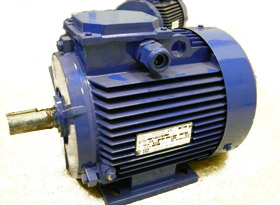
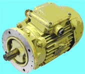
Closed blown motor (degree of protection IP44)
Heat resistance classes of the insulation system of the electric motor
Insulating materials used in electric motors are divided into classes according to heat resistance.
The insulating material is classified into one or another class depending on the maximum permissible temperature. Engines operate at different ambient temperatures.
 For the rated ambient temperature for temperate climates, unless otherwise specified, a temperature of 40 °C is taken. The maximum permissible temperature rise of the motor winding is obtained by subtracting 40 from the temperature index of the insulation system.
When choosing a higher heat resistance class (e.g. F instead of B), two selection goals can be achieved:
1) increasing engine power with a constant theoretical service life,
2) increase in service life and reliability with constant power. In most cases, the use of more heat-resistant insulation is intended to improve the reliability of the motor under severe operating conditions.