Tenometers — tensometric measuring transducers
Strain gauge sensor — a parametric resistive transducer that converts the deformation of a rigid body caused by a mechanical stress applied to it into an electrical signal.
A resistive pressure gauge is a base with a sensitive element attached. The principle of strain measurement using a strain gauge is that the resistance of the strain gauge changes during the strain. The effect of the change of resistance of a metallic conductor under the action of all-round compression (hydrostatic pressure) was discovered in 1856 by Lord Kelvin and in 1881 by OD Hvolson.
In its modern form, a strain gauge structurally represents a strain resistor, the sensitive element of which is made of a tension-sensitive material (wire, foil, etc.), fixed with a binder (glue, cement) on the part under investigation (Figure 1). To connect the sensing element to the electrical circuit, the strain gauge has wires.Some strain gauges design for easier installation, they have a pad located between the sensitive element and the part under test, as well as a protective element located above the sensitive element.
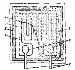
Figure 1 Schematic of the strain gauge: 1- sensitive element; 2- binder; 3- substrate; 4- investigated detail; 5- protective element; 6- block for soldering (welding); 7-wire wiring
With all the variety of tasks solved using strain gauge transducers, two main areas of their use can be distinguished:
— study of the physical properties of materials, deformations and stresses in parts and structures;
— the use of strain gauges to measure mechanical values that are converted into deformation of an elastic element.
The first case is characterized by a significant number of voltage measurement points, wide ranges of changes in environmental parameters, as well as the impossibility of calibrating the measurement channels. In this case, the measurement error is 2-10%.
In the second case, the sensors are calibrated according to the measured value and the measurement errors are in the range of 0.5-0.05%.
The most striking example of the use of strain gauges is the balance. The scales of most Russian and foreign manufacturers are equipped with strain gauges. Load cell scales are used in various industries: non-ferrous and ferrous metallurgy, chemical, construction, food and other industries.
The principle of operation of electronic scales is reduced to measuring the force of gravity acting on the load cell by converting the resulting changes, such as deformation, into a proportional output electrical signal.
The wide use of tensor resistors is explained by a number of their advantages:
— small size and weight;
— low inertia, which allows the use of strain gauges for both static and dynamic measurements;
— have a linear characteristic;
— allow measurements to be made remotely and at many points;
— the method of their installation on the examined part does not require complex devices and does not distort the deformation field of the examined part.
And their disadvantage, which is temperature sensitivity, can be compensated for in most cases.
Types of converters and their design features
The operation of strain gauges is based on the deformation effect phenomenon, which consists in a change in the active resistance of the wires during their mechanical deformation. The characteristic of the deformation effect of the material is the coefficient of relative deformation sensitivity K, defined as the ratio of the change in resistance to the change in the length of the conductor:
k = er / el
where er = dr / r — the relative change in the resistance of the conductor; el = dl / l — the relative change in the length of the wire.
During the deformation of solid bodies, the change in their length is associated with a change in volume, and their properties, in particular, the resistance value, also change. Therefore, the value of the sensitivity coefficient in the general case should be expressed as
K = (1 + 2μ) + m
Here, the quantity (1 + 2μ) characterizes the change in resistance associated with a change in the geometric dimensions (length and cross-section) of the conductor, and — a change in the resistance of the material associated with a change in its physical properties.
If semiconductor materials are used in the production of the tensor, the sensitivity is mainly determined by the change in the properties of the lattice material during its deformation and K »m and can vary for different materials from 40 to 200.
All existing converters can be divided into three main types:
— wire;
— foil;
— a movie.
Wire telemeters are used in the technique of measuring non-electric quantities in two directions.
The first direction is the use of the deformation effect of a conductor in a state of volume compression, when the natural input value of the transducer is the pressure of the surrounding gas or liquid. In this case, the transducer is a coil of wire (usually manganin) placed in the area of the measured pressure (liquid or gas). The output value of the converter is the change in its active resistance.
The second direction is to use the tension effect of the tension wire made of a tension-sensitive material. In this case, voltage sensors are used in the form of "free" converters and in the form of glued ones.
"Free" strain gauges are made in the form of one or a row of wires, fixed at the ends between the movable and immovable parts and, as a rule, simultaneously perform the role of an elastic element. The natural input value of such transducers is very little movement of the moving part.
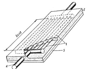
The device of the most common type of bonded wire strain gauge is shown in figure 2. A thin wire with a diameter of 0.02-0.05 mm, placed in a zigzag pattern, is glued to a strip of thin paper or lacquer foil. Leaded copper wires are connected to the ends of the wire. The top of the converter is covered with a layer of varnish and sometimes sealed with paper or felt.
The transducer is usually installed so that its longest side is oriented in the direction of the measured force. Such a transducer, glued to the test specimen, perceives the deformations of its surface layer. Thus, the natural input value of the glued transducer is the deformation of the surface layer of the part to which it is glued, and the output is the change in resistance of the transducer proportional to this deformation. Generally, glued sensors are used much more often than non-glued ones.
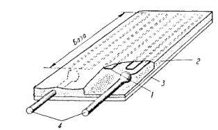
Figure 2 - bonded wire strain gauge: 1 - strain gauge wire; 2- glue or cement; 3- cellophane or paper backing; 4-wire wires
The measuring base of the transducer is the length of the part occupied by the wire. The most commonly used transducers are 5-20 mm bases with a resistance of 30-500 ohms.
In addition to the most common contour strain gauge design, there are others. If it is necessary to reduce the measuring base of the transducer (to 3 — 1 mm), it is done by the winding method, which consists in winding a spiral of load-sensitive wire on a mandrel of circular cross section on a tube of thin paper. This tube is then glued, removed from the mandrel, flattened, and the wires are attached to the ends of the wire.
When it is necessary to obtain a large current from a circuit with a thermoconverter, they often use "Powerful" strain gauges with a coiled wire... They consist of a large number (up to 30 — 50) wires connected in parallel, differ in large sizes (length of the base 150 — 200 mm) and enable a significant increase in the current passed through the converter (Figure 3).
Drawing 3- Tenometer with low resistance ("powerful"): 1 — strain gauge wire; 2- glue or cement; 3- cellophane or paper backing; 4 pin wire
Wire probes have a small contact area to the sample (substrate), which reduces leakage currents at high temperatures and leads to a higher isolation voltage between the sensitive element and the sample.
Foil load cells are the most popular version of adhesive load cells. Foil transducers are a strip of foil 4-12 microns thick, on which a portion of the metal is selected by etching in such a way that the rest of it forms the lead grid shown in Figure 4.
In the production of such a grid, any pattern of the grid can be foreseen, which is a significant advantage of foil strain gauges. In image 4, a shows the appearance of a foil transducer designed to measure linear stress states, in fig. 4, c — a foil transducer glued to the shaft for measuring torques, and in fig. 4, b — glued to the membrane.
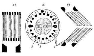
Drawing 4- Foil converters: 1- adjusting loops; 2- bends sensitive to membrane tensile forces; 3- rotations sensitive to the compressive forces of the diaphragm
A serious advantage of foil converters is the possibility of increasing the cross-section of the ends of the converter; welding (or soldering) of wires can be done in this case much more reliably than with wire converters.
Foil deformers, compared to wire ones, have a higher ratio of the surface of the sensitive element to the cross-sectional area (sensitivity) and are more stable at critical temperatures and sustained loads. The large surface area and small cross-section also ensure good temperature contact between the sensor and the sample, which reduces self-heating of the sensor.
For the production of foil strain gauges, the same metals are used as for telenometers (constantan, nichrome, nickel-iron alloy, etc.), and other materials are also used, for example, titanium-aluminum alloy 48T-2, which measures strains up to 12 %, as well as a number of semiconductor materials.
Film tensors
In recent years, another method for mass production of bonded resistance strains has emerged, which consists in vacuum sublimation of a strain-sensitive material and its subsequent condensation on a substrate sprayed directly onto the workpiece. Such transducers are called film transducers. The small thickness of such strain gauges (15-30 microns) gives a significant advantage when measuring strains in dynamic mode at high temperatures, where strain measurements are a specialized area of research.
A number of film strain gauges based on bismuth, titanium, silicon or germanium have been made in the form of a single conductive strip (Figure 5).Such transducers do not have the disadvantage of reducing the relative sensitivity of the transducer compared to the sensitivity of the material from which the transducer is made.
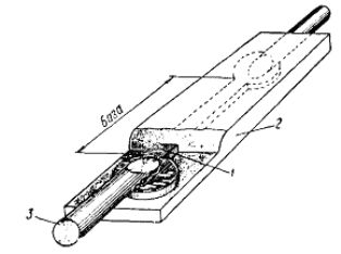
Figure 5- Film strain gauge: 1- strain gauge film; 2- lacquer foil; 3-pin wire
The strain gauge coefficient of a metal film-based transducer is 2-4, and its resistance varies from 100 to 1000 ohms. Transducers made on the basis of semiconductor film have a coefficient of the order of 50-200 and are therefore more sensitive to the applied voltage. In this case, there is no need to use amplifier circuits, since the output voltage of the semiconductor strain-resistor bridge is approximately 1 V.
Unfortunately, the resistance of a semiconductor converter varies with the applied voltage and is essentially non-linear over the entire voltage range, and is also highly temperature dependent. Thus, although an amplifier is required when working with a metal film deformer, the linearity is very high and the temperature effect can be easily compensated.