Transformers: purpose, classification, nominal data for transformers
Transformers — electromagnetic static converters of electrical energy. Transformers are electromagnetic devices that are used to convert alternating current of one voltage to alternating current of another voltage at the same frequency and to electromagnetically transfer electrical energy from one circuit to another.
«A transformer is a static electromagnetic device designed to convert one — primary — alternating current system into another — secondary with the same frequency, which usually has other characteristics, in particular different voltage and different current» (Piotrovsky LM Electric machines).
The main purpose of transformers is to change the AC voltage. Transformers are also used to convert the number of phases and frequency.
Current transformers are called devices designed to convert a current of any magnitude into a current admissible for measurements with normal instruments, as well as for powering various relays and coils of electromagnets.The number of turns of the secondary winding of the current transformer w2> w1.
A characteristic of current transformers is their operation in a mode close to short circuit, since their secondary winding is always closed with a small resistance.
Voltage transformers are called devices designed to convert high-voltage alternating current into low-voltage alternating current and power parallel coils of meters and relays. The principle of operation and design of voltage transformers is similar to the principle of operation of power transformers. The number of turns of the secondary winding is w2 <w1, since all measuring voltage transformers are step-down type.
The principle of operation of voltage transformers:
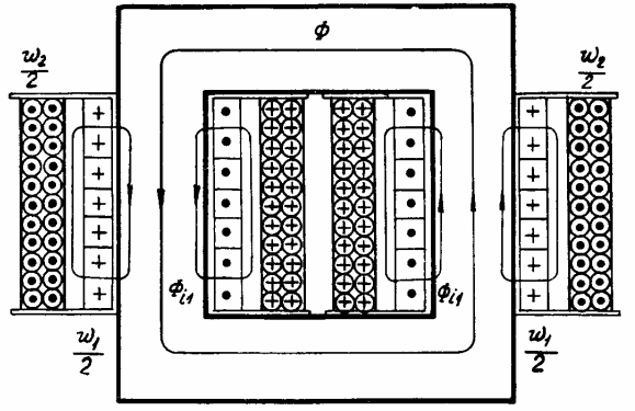
The peculiarity of the operation of the voltage measuring transformer is that its secondary winding is always closed to a high resistance, and the transformer works in a mode close to the idle mode, since the connected devices consume negligible current.
The most common are supply voltage transformers, which are produced by the electrical industry for a capacity of over one million kilovolt-amperes and for voltages up to 1150 — 1500 kV.
Power Transformer Design:
For the transmission and distribution of electrical energy, it is necessary to increase the voltage of turbogenerators and hydrogenerators installed in power plants from 16 — 24 kV to voltages of 110, 150, 220, 330, 500, 750 and 1150 kV used in transmission lines and after reduce this again to 35; ten; 6; 3; 0.66; 0.38 and 0.22 kV for energy use in industry, agriculture and everyday life.
 Since multiple transformations take place in power systems, the power of transformers is 7-10 times greater than the installed power of generators in power plants.
Power transformers are mainly manufactured for a frequency of 50 Hz.
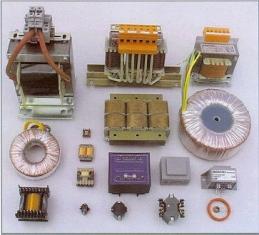
Low-power transformers are widely used in various electrical installations, information transmission and processing systems, navigation and other devices. The frequency range at which transformers can operate is from a few hertz to 105 Hz.
According to the number of phases, transformers are divided into single-phase, two-phase, three-phase and multiphase. Power transformers are mainly manufactured in three-phase design. For use in single-phase networks are produced single-phase transformers.
Classification of transformers by the number and connection schemes of the windings
Transformers have two or more windings that are inductively connected to each other. The windings that consume power from the network are called primary... The windings that supply electrical energy to the consumer are called secondary.
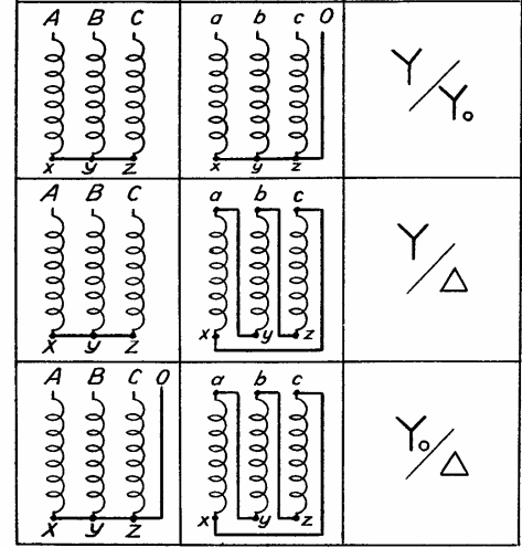
Polyphase transformers have windings connected in a multi-beam star or polygon. Three-phase transformers have a star-delta three-beam connection.
Connection diagrams of the winding of a power transformer:
Step-up and step-down transformers
Depending on the ratio of the voltages of the primary and secondary windings, transformers are divided into step-up and step-down... V step-up transformer the primary winding is low voltage and the secondary is high. V step down transformer reverse, the secondary is low voltage and the primary is high.
They are called transformers with one primary and one secondary winding with a double winding... Quite widespread transformers with three windings three windings for each phase, for example two on the low voltage side, one on the high voltage side or vice versa. Polyphase transformers may have multiple windings for high and low voltage.
Classification of transformers by design
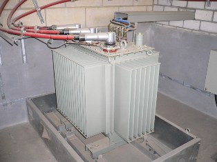
By design, power transformers are divided into two main types — oil and dry.
V oil transformers the magnetic circuit with windings is located in a reservoir filled with transformer oil, which is a good insulator and cooling agent.
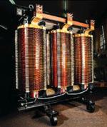
Dry transformers are air cooled. They are used in residential and industrial premises where operation of an oil-immersed transformer is undesirable. Transformer oil is flammable and can damage other equipment if the tank is not sealed. Read more about this type of transformer here: Dry transformers
In accordance with the normative documents, the design characteristics of the transformer are reflected in the designation of its type and cooling systems.
Transformer Type:
- Autotransformer (for single-phase O, for three-phase T)-A
- Low Voltage Coil — P
- Liquid dielectric shielding with nitrogen blanket without expander — Z
- Cast resin execution — L
- Three-winding transformer — T
- Load Switch Transformer-N
- Natural air-cooled dry transformer (usually the second letter in the type designation), or version for auxiliary needs of power plants (usually the last letter in the type designation) — C
- Cable seal — K
- Flange inlet (for entire transformer substations) — F
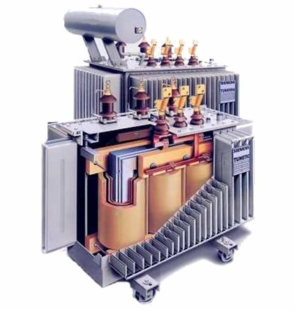
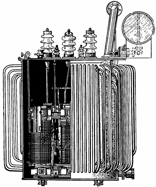
Power oil transformer TM-160 (250) kVA
Dry transformer cooling systems:
- Natural air with open design — S
- Natural air with a protected design — SZ
- Natural air sealed design — SG
- Air with forced air circulation — SD
Cooling systems for oil transformers:
- Natural circulation of air and oil — M
- Forced air circulation and natural oil circulation — D
- Natural air circulation and forced oil circulation with non-directed oil flow — MC
- Natural air circulation and forced oil circulation with directed oil flow — NMC
- Forced air and oil circulation with non-directional oil flow — DC
- Forced Air and Oil Circulation with Directional Oil Flow — NDC
- Forced circulation of water and oil with non-directional flow of oil — C
- Forced water and oil circulation with directed oil flow — NC
Cooling systems for transformers with non-flammable liquid dielectric:
- Liquid dielectric cooling with forced air circulation — ND
- Non-flammable Liquid Dielectric Forced Air Directed Liquid Dielectric Flow Cooling - NND
Related Articles:
Power transformers — device and principle of operation
Power transformers: rated operating modes and values
Power transformer cooling systems
Automotive transformers
Along with transformers, they are widely used autotransformers, where there is an electrical connection between the primary and secondary windings. In this case, the power from one winding of the autotransformer to another is transmitted both by a magnetic field and due to electrical communication.Autotransformers are built for high power and high voltage and are used in power systems and are also used for voltage regulation in low power installations.
Rated data for transformers
The rated data of the transformer, for which it is designed with a factory warranty of 25 years, is indicated on the nameplate of the transformer:
-
nominal apparent power Snom, KV-A,
-
rated line voltage Ulnom, V or kV,
-
nominal current of the AzIn A line,
-
nominal frequency is, Hz,
-
number of phases,
-
circuit and group for connecting coils,
-
short circuit voltage Uc,%,
-
mode of operation,
-
cooling method.
The plate also contains the data necessary for installation: total weight, oil weight, weight of the movable (active) part of the transformer. The transformer type is specified in accordance with GOST for the transformer brands and manufacturer.
Nominal power of a single-phase transformer Snom =U1nom I1nom, three-phase
where U1lnom, U1phnom, I1lnom and I1fnom — nominal respectively line and phase values of voltages and currents.
Transformer rated voltage is the line-to-line no-load voltages of the primary and secondary windings of the transformer. Per rated currents of the primary and secondary windings of the transformer, the currents are taken calculated according to the rated power at rated primary and secondary voltage.
Due to their common construction and calculation methods, transformers can be classified as reactors, saturation chokes, and superconducting inductive storage devices.