Travel microswitches: device and technical characteristics
Microswitches are widely used in electrical engineering, with high reliability but with fewer switching capabilities than limit switches of normal design.
Switch for micro switches alternating current up to 2.5 A at a voltage of 380 V. The operating stroke of the microswitch is 0.2 mm, the additional stroke is 0.1 mm. The force during the forward stroke is (4 — 6) N.
In fig. 1, and shows the MP6000 series microswitch design. In the plastic case 1 there are fixed contacts 8 and 9, fixed on the metal bushings 7 and 10. The movable contact 5 of the lever type is made in the form of a flat spring with two longitudinal slots. The spring is fixed on the sleeve 2, and its end parts rest on the fork 3; bending, they form an instant switching device. The actuating element of the microswitch consists of a pusher 4, which passes into a hole in the housing cover 6, which is connected to the body by a pin 11. The lower part of the pusher has a plastic washer with a spherical surface.
Under the influence of the limiter, the pusher presses the middle part of the flat spring 5, which in the direct actuation position instantly moves to another position of stable equilibrium, switching the contacts of the microswitch. External connections of the microswitch are made through terminals 12.
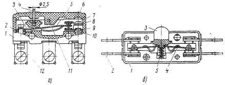
Microswitches: a — MP6000 series, b — VP61 type
In fig. 1b shows a diagram of a VP61 microswitch that has bridge contacts with double circuit breaker. This allows, with small overall dimensions, the microswitch to switch an alternating current of 6 A.
 The microswitch consists of a housing 1, contact racks 2 with fixed contacts and a plastic pusher 3. The bridge contact is made in the form of a bursting spring with two stable positions. When the pusher is moved, the microswitch spring snaps and produces an immediate opening of the switching contacts. The return to the initial position is carried out to spring 5.
There are open design micro switches that are built into the automation device.
In fig. 2 shows an example of such a switch with a closing mechanism. It consists of a spring lever contact block 1 with switching contacts, a lever pusher 2 with a roller and a flat accelerating spring 3. When the roller is pressed, the lever 2 rotates and the spring 3 switches the movable contact of the microswitch. The contact pressure is determined only by the setting of the contact node and practically does not change with further rotation of the lever 2.
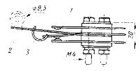
Microswitch with open path
Micro travel switches have very little additional actuator travel.This requires precise execution of the control stop and the unchanged distance between the microswitch housing and the limiter axis. If these conditions are difficult to meet, apply intermediate mechanical elements that increase the extra travel of the microswitch. These can be telescopic stops with an internal spring, levers of the first or second type, cam mechanisms, the direction of movement of which is perpendicular to the direction of movement of the driving element of the microswitches.
Micro Proximity Switches
Increasing requirements for speed, accuracy and reliability of positional systems of discrete automation determined the need for proximity switches... Non-contact motion switches can be divided into three groups.
In non-contact limit switches of the first group, there is no direct mechanical interaction between the moving block of the machine tool and the drive element. The switching device of such switches has a contact design.
In the switches of the second group, on the contrary, the switching device is made non-contact, and the mechanism of the machine has direct contact with the drive device of the switch. Such limit switches can be called electrically non-contact.
Finally, the limit switches of the third group are completely contactless devices, in which the movement of the machine tools is transmitted contactlessly to the limit switch and then also contactlessly converted into an electrical signal. Such limit switches are sometimes called static.
An example is reed switch traveling microswitches… High reliability, fast response, small size of reed switches make these switches promising for use in various fields of mechanical engineering.
Principle of Operation Reed Switch Traveling Microswitches Let us explain with the help of fig. 3. The limit switch consists of a rectangular permanent magnet 1 (Fig. 3, a), fixed on the movable block of the machine, and a reed switch 2, mounted on a fixed main part. The axis of the magnet is parallel to the axis of the reed switch bulb.
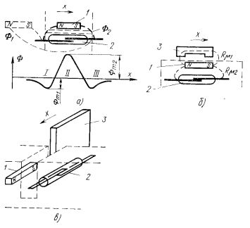
Reed switch microswitches: a, 6 — flat design with moving magnet and moving shunt, b — slot design with ferromagnetic shield
The change in magnetic flux passing through a reed switch is complex. Initially, when the distance between the reed switch and the magnet is large, the magnetic flux in the gap of the reed switch closes along the path F1 (dotted line in Fig. 3, a). This flux is then shunted by one of the reed switch springs and reduced to zero, after which the direction of the magnetic flux will reverse as the position of the magnetic poles relative to the reed switch plates will be changed. This flow is designated as F2.
The reed switch can be actuated three times along the travel path in zones / — ///. If such a sequence of operation of the reed switch is unacceptable, then it is necessary to calculate the magnetic system so that Фm1 had a smaller flux of actuation of the reed switch.This can be achieved by changing the configuration of the permanent magnet and the gap between the magnet and the reed switch.
In fig. 3b shows an example of a more compact limit switch, in which the permanent magnet 1 and the reed switch 2 are located in one housing and fixed fixedly on the machine.