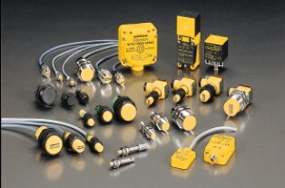
Inductive sensors
An inductive sensor is a parametric type transducer whose operating principle is based on change inductance L or the mutual inductance of the winding with the core, due to a change in the magnetic resistance RM of the magnetic circuit of the sensor into which the core enters.
Inductive sensors are widely used in industry to measure displacements and cover the range from 1 μm to 20 mm. It is also possible to use an inductive sensor to measure pressures, forces, gas and liquid flow rates, etc. In this case, the measured value is converted using various sensitive elements into a displacement change and then this value is fed to an inductive measuring transducer.
In the case of pressure measurement, the sensitive elements can be made in the form of elastic membranes, sleeve, etc. They are also used as proximity sensors, which are used to detect various metallic and non-metallic objects in a non-contact manner on the yes or no principle.
Advantages of inductive sensors:
-
simplicity and strength of the construction, without sliding contacts;
-
ability to connect to power frequency sources;
-
relatively high output power (up to tens of watts);
-
significant sensitivity.
Disadvantages of inductive sensors:
-
the accuracy of operation depends on the stability of the supply voltage by frequency;
-
operation is only possible with alternating current.
Types of inductive converters and their design features
According to the construction scheme, inductive sensors can be divided into single and differential. An inductive sensor contains one measuring branch, a differential one - two.
In a differential inductive sensor, when the measured parameter changes, the inductance of two identical coils changes simultaneously and the change occurs by the same value but with the opposite sign.
As it is known, inductance of the coil:

where W is the number of turns; F — magnetic flux penetrating it; I — the current passing through the coil.
Current is related to MDS by the ratio:

Where we get:

where Rm = HL / Ф is the magnetic resistance of the inductive sensor.
Consider, for example, a single inductive sensor. Its operation is based on the property of an air-gap choke to change its inductance as the air-gap value changes.
The inductive sensor consists of a yoke 1, a coil 2, an armature 3 — held by springs. An alternating current supply voltage is supplied to coil 2 through the load resistance Rn. The current in the load circuit is defined as:
where rd is the active resistance of the choke; L is the inductance of the sensor.
Because the active resistance of the circuit is constant, then a change in the current I can only occur due to a change in the inductive component XL = IRn, which depends on the size of the air gap δ.
To each value δ corresponds to a certain value I, which creates a voltage drop on the resistance Rn: Uout = IRn — is the output signal of the sensor. You can derive the analytical dependence Uout = f (δ) provided the gap is small enough and the stray fluxes can be neglected, and the iron magnetoresistance Rmw can be neglected compared to the air gap magnetoresistance Rmw.
Here is the final expression:
In real devices, the active resistance of the circuit is much less than the inductive one, then the expression reduces to the form:
The dependence Uout = f (δ) is linear (in the first approximation). The actual feature is as follows:
The deviation from linearity at the beginning is explained by the accepted assumption Rmzh << Rmv.
At small d, the magnetoresistance of iron is commensurate with the magnetoresistance of air.
The deviation at large d is explained by the fact that at large d RL becomes commensurate with the value of the active resistance — Rn + rd.
In general, the considered inductive sensor has a number of significant disadvantages:
-
the phase of the current does not change when the direction of movement is changed;
-
if it is necessary to measure the displacement in both directions, it is necessary to set the initial air gap and therefore the current I0, which is inconvenient;
-
the load current depends on the amplitude and frequency of the supply voltage;
-
during the operation of the sensor, the force of attraction to the magnetic circuit acts on the armature, which is not balanced by anything and therefore introduces an error into the operation of the sensor.

Differential (reversible) inductive sensors (DID)
Differential inductive sensors are a combination of two irreversible sensors and are made in the form of a system consisting of two magnetic circuits with a common armature and two coils. Differential inductive sensors require two separate power supplies, for which an isolation transformer 5 is usually used.
The shape of the magnetic circuit can be differential-inductive sensors with a W-shaped magnetic circuit, recruited by bridges of electrical steel (for frequencies above 1000Hz, iron-nickel-permola alloys are used), and cylindrical with a dense circular magnetic circuit. The choice of the shape of the sensor depends on its constructive combination with the controlled device. The use of a W-shaped magnetic circuit is due to the convenience of assembling the coil and reducing the size of the sensor.
To power the differential-inductive sensor, a transformer 5 with an output for the middle point of the secondary winding is used. The device 4 is included between it and the common end of the two coils. The air gap is 0.2-0.5 mm.
At the middle position of the armature, when the air gaps are the same, the inductive resistances of the coils 3 and 3' are the same, therefore the values of the currents in the coils are equal to I1 = I2 and the resulting current in the device is 0.
With a slight deviation of the armature in one direction or another, under the influence of the controlled value X, the values of the gaps and inductances change, the device registers the differential current I1-I2, this is a function of the armature displacement from the middle position. The difference in currents is usually recorded using a magnetoelectric device 4 (microammeter) with a rectifier circuit B at the input.
The characteristics of the inductive sensor are:
The polarity of the output current remains unchanged regardless of the sign of the change in the impedance of the coils. When the direction of deviation of the armature from the middle position changes, the phase of the current at the output of the sensor changes in reverse (by 180 °). When using phase-sensitive rectifiers, an indication of the armature's direction of travel can be obtained from the middle position. The characteristics of a differential inductive sensor with a phase-frequency filter are as follows:
Inductive sensor conversion error
The information capacity of an inductive sensor is largely determined by its error when converting the measured parameter. The total error of an inductive sensor consists of a large number of error components.
The following inductive sensor errors can be distinguished:
1) Error due to non-linearity of the characteristic. The multiplicative component of the total error. Due to the principle of inductive conversion of the measured value, which is the basis of the operation of inductive sensors, it is essential and in most cases determines the measuring range of the sensor. Mandatory subject to evaluation during sensor development.
2) Temperature error. Random ingredient.Due to the large number of temperature-dependent parameters of the sensor components, the error of the component can reach large values and is significant. To be evaluated in sensor design.
3) Error due to the influence of external electromagnetic fields. The random component of the total error. It occurs due to the induction of EMF in the sensor winding by external fields and due to a change in the magnetic characteristics of the magnetic circuit under the influence of external fields. In industrial premises with power electrical installations, magnetic fields with induction T and frequency mainly 50 Hz are detected.
Since the magnetic cores of inductive sensors work at inductions of 0.1 — 1 T, the share of external fields will be 0.05-0.005% even in the absence of shielding. Screen input and the use of a differential sensor reduce this proportion by about two orders of magnitude. Thus, the error due to the influence of external fields should only be considered when designing sensors with low sensitivity and with the impossibility of sufficient shielding. In most cases, this error component is not significant.
4) Error due to the magnetoelastic effect. It arises due to the instability of the deformations of the magnetic circuit during sensor assembly (additive component) and due to changes in deformations during sensor operation (arbitrary component). Calculations taking into account the presence of gaps in the magnetic circuit show that the influence of the instability of mechanical stresses in the magnetic circuit causes instability of the output signal of the order sensor, and in most cases this component can be specifically neglected.
5) Error due to strain gauge effect of coil.Random ingredient. When winding the sensor coil, a mechanical tension is created in the wire. A change in these mechanical stresses during sensor operation results in a change in the resistance of the coil to direct current and therefore a change in the output signal of the sensor. Usually for properly designed sensors, that is, this component should not be considered specifically.
6) Deviation from the connecting cable. It occurs due to the instability of the electrical resistance of the cable under the influence of temperature or deformations and due to the induction of EMF in the cable under the influence of external fields. Is the random component of the error. In case of instability of the own resistance of the cable, the error of the output signal of the sensor. The length of connecting cables is 1-3 m and rarely more. When the cable is made of cross-sectional copper wire, the resistance of the cable is less than 0.9 Ohm, resistance instability. Since the sensor impedance is typically greater than 100 ohms, the error in the sensor output can be as large as Therefore, for sensors with low operating resistance, the error must be estimated. In other cases, it is not significant.
7) Design errors.They arise under the influence of the following reasons: the influence of the measuring force on the deformations of the sensor parts (additive), the influence of the difference in the measuring force on the instability of the deformations (multiplicative), the influence of the guides of the measuring rod during the transmission of the measuring pulse (multiplicative), the instability of the transfer of the measuring pulse due to gaps and backlash of the moving parts (random). Design errors are primarily determined by defects in the design of the mechanical elements of the sensor and are not specific to inductive sensors. The evaluation of these errors is carried out according to the known methods for evaluating the errors of the kinematic transmissions of the measuring devices.
8) Technological errors. They arise as a result of technological deviations in the relative position of sensor parts (additive), the dispersion of the parameters of parts and coils during production (additive), the influence of technological gaps and tightness in the connections of parts and in guides (arbitrary).
Technological errors in the manufacturing of the mechanical elements of the sensor structure are also not specific to the inductive sensor; they are evaluated using the usual methods for mechanical measuring devices. Errors in the manufacturing of the magnetic circuit and the sensor coils lead to dispersion of the parameters of the sensors and to difficulties arising in ensuring the interchangeability of the latter.
9) Sensor aging error.This error component is caused, firstly, by the wear of the moving elements of the sensor structure and, secondly, by the change over time of the electromagnetic characteristics of the magnetic circuit of the sensor. The error should be considered accidental. When evaluating the error due to wear, the kinematic calculation of the sensor mechanism in each specific case is taken into account. At the sensor design stage, in this case, it is recommended to set the service life of the sensor under normal operating conditions, during which the additional wear error will not exceed the specified value.
The electromagnetic properties of materials change over time.
In most cases, the pronounced processes of changing the electromagnetic characteristics end within the first 200 hours after the heat treatment and demagnetization of the magnetic circuit. In the future, they remain practically constant and do not play a significant role in the overall error of the inductive sensor.
The above consideration of the components of the error of an inductive sensor makes it possible to evaluate their role in the formation of the total error of the sensor. In most cases, the determining factor is the error from the non-linearity of the characteristic and the temperature error of the inductive converter.