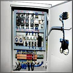
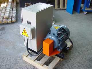
Protection of control and signaling circuits against short circuits
The main type of protection for the control and signaling circuit is short-circuit protection by means of fuses or circuit breakers.
The control circuit is connected to the phase-to-phase voltage through a separate packet switch and is protected by separate fuses. Sometimes, when magnetic starters are used, a fuse is installed in only one phase of the control circuit.
For small motor control circuits (up to 10 kW), the control circuit is protected by the same fuses as the main circuit.
If electrical devices made for a voltage of 220 V are used to control electric motors, then the control circuit is powered by a separate AC network or phase voltage of the network with a neutral wire. A single-phase step-down transformer with a secondary voltage of 110 V, in some cases 36 V or less (when such a voltage is required for safety reasons) is also used.
Supplying control circuits with reduced voltage through a step-down transformer increases the reliability of the control devices. It should be borne in mind that in order to ensure the safety of the service personnel, the inclusion of the control equipment to the phase voltage can be allowed only if certain requirements are met, namely:
1) if at least two stages of the power distribution network, starting from the motor, are equipped with automatic switches (or maximum relays — for an electric motor);
2) if, when they are protected by fuses using special devices, a simultaneous shutdown of the three phases of the motor is achieved during the combustion of each stage of the two-phase fuses.
For this purpose, an additional voltage relay can be used, which monitors the voltage between two phases, for example A and B, while the control circuit is connected to the third phase C.
The closing contact of the relay is introduced into the coil circuit of the linear contactor or starter, the neutral terminal of which must be reliably connected to the neutral conductor or to the grounded body of the electrical apparatus (electrical cabinet).
For a direct current control circuit, voltages of 110 and 220 V are usually used. In these circuits, where low-current equipment, electromagnetic couplings, etc. are used, the supply voltage does not exceed 24 V.
Protection of the control circuit is most often carried out by fuses of the PR2 type, as well as various fuses with a thread (plug) for currents up to 60 A.
Selection of fuses to protect the control circuits
The selection of fuses for a control circuit with voltage Un can be made according to the formula
Self-employed≥ (∑Pр + 0.1 .Pv) / Un
where .PR — the largest total power consumed by the windings of electrical devices (electromagnetic starters, intermediate relays, time relays, executive electromagnets) and signal lamps, etc. with simultaneous operation, VA or W,
.Pv — the highest total power consumed when the coils of simultaneously connected devices are switched on (initial power), VA or W.
If currents and not powers are known, this formula can be written in the form
Self-employed ≥ ∑Ip + 0.1 ∑Iv
Selection of circuit breakers for protection of control circuits
Instead of package switches and fuses, circuit breakers can be installed, for example double pole with electromagnetic and combination releases.
The rated current of the combined release of the breaker to protect the control circuits is selected according to the formula
Azusta e-mail magn. ≥ 1.5 ( .Pр + ∑ (P 'v — P 'R) / Un)
or
Azusta e-mail magn. ≥ 1.5 ∑Ip + ∑(I ‘v — I ‘R)


