DC motor device
DC motor — an electromechanical device that converts constant electrical energy into mechanical energy.
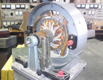
The DC electric motor consists of a stationary part - a frame and a rotating part - an armature.
Stanina - a hollow steel cylinder, on the inner surface of which an even number of main poles of a DC motor protrude... These poles are assembled from thin sheets of electrical steel, insulated from each other with varnish and end with flared parts - pole parts for distributing the magnetic induction in the air gap according to a law close to the trapezoidal one.
The lines passing through the middle of the poles and the center of the shaft of the DC motor are called its longitudinal magnetic axes.
One or more are located at the poles. DC excitation coils that are interconnected so as to produce alternating polarity of the poles that excite the primary stationary magnetic field cars.
Exciting coils with a large number of turns of thin wire and significant resistance have leads to terminals marked Ш1 and Ш2, and field coils with a small number of turns of thick wire and low resistance have leads to terminals marked C1 and C2.
Between the main poles of the DC motor there are additional poles that are smaller than the main ones and made of solid steel. Usually, the number of additional poles is equal to the number of the main ones, and only in electric motors with a nominal power of up to 2 — 2.5 kW, their number is reduced by half. On these poles there is a winding of additional poles with a small number of turns of thick wire, low resistance, with leads to terminals marked D1 and D2.
In heavy-duty DC motors, the poles have grooves parallel to the axis of the shaft, where a compensating winding with a small number of turns of thick wire and low resistance with leads to terminals marked K1 and K2.
DC Motor Tutorial
Exciting windings, additional pole windings and compensation winding are made with insulated copper wire. For wires with a significant cross-section, the winding of the additional poles is carried out with an uninsulated copper busbar wound with a spiral on a narrow edge, with insulation laid both between the turns and between them and the pole itself.
The excitation strength of the magnetic field of a DC motor, depending on its size, varies from 0.5 to 5% of its rated power.
Between the surfaces of the poles and the magnetic circuit of the armature there is an air gap, the radial size of which, depending on the nominal power of the electric motor and its speed, usually varies from a few fractions of a millimeter to ten millimeters.
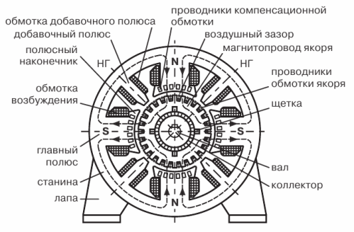
DC motor device: 1 — frame, 2 — main pole, 3 — field coil, 4 — pole tip, 5 — additional pole, 6 — additional pole coil, 7 — compensating winding wires, 8 — air gap, 9 — magnetic circuit on the anchor, 10 — wires for winding the anchor, 11 — brush, 12 — shaft, 13 — collector, 14 — claw.
Drum type armature - a toothed cylinder mounted on the shaft of a direct current electric motor, assembled from packages consisting of thin lacquered insulating sheets of electrical steel with grooves on the outer surface. Radial ventilation ducts are located between the packages, and the armature ducts are filled with insulated copper wires that are connected at the ends to each other in sections that enter the armature winding.
Section - the main element of the armature winding of one or several series-connected turns, the beginning and end of which are soldered to two collector plates, as a result of which the end of one section and the beginning of the next are connected to the same collector plate.
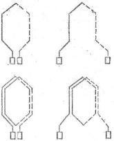
One- and two-turn armature windings of electric motors with direct current: a — loop, b — wave
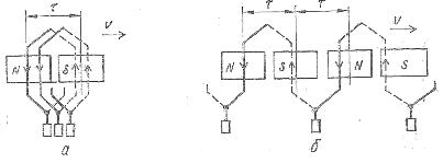
Connection of sections of armature windings of DC motors: a — loop, b — wave
Collector — a hollow cylinder made of small plates of trapezoidal tightly drawn copper, isolated by gaskets and micanite cuffs from each other and from the shaft.
For technological reasons, the armature winding is double-layered, placed in each groove of its magnetic circuit on two sides of different sections: in the upper layer of one groove - one side of the section shown with a solid line, and in the lower layer of another groove, located under the opposite main pillar, — the other side of the same section shown by a dotted line. The slots in which the two sides of the same section are located are offset relative to each other by an amount close to or equal to the pole separation ? — the distance along the circumference of the anchor between the axes of adjacent main pillars.
Regardless of the type of armature winding - loop or wave - it forms a closed circuit, divided into groups of fixed graphite, carbon-graphite, copper-graphite or bronze-graphite brushes, pressed by springs to the collector, in an even number of identical parallel branches along armature winding clamp ratio labeled R1 and R2. With a loop or parallel winding, the number of parallel branches is equal to the number of main poles of the electric motor, and with a wave or series, the winding is always equal to two.
Groups of brushes, mounted in brush holders, are mounted evenly around the circumference of the collector in front of the middle of the main poles, so as to join those sections of the armature winding which are currently on geometric neutral armatures — fixed lines passing through the center on the shaft of the machine along the axes of the additional poles. Geometric neutrals are located along the normals to the magnetic lines of the main field of the machine, and their number is equal to the number of pairs of main poles.
When the brushes are located on the collector plates corresponding to the sections of the armature winding located on geometric neutrals, and at idle speed of the electric motor, e.g. d. s induced in moving conductors in each parallel branch of the armature winding are directed according to and e. etc. c. between brushes of different polarity reaches the highest value. When the brushes are moved around the circumference of the collector in any direction, this e. etc. p. decreases, since wires with oppositely directed emf appear in the parallel-connected branches of the armature winding. etc. with
The brush holders are mounted on the pins of the rotating brush, from which they are electrically isolated. With the help of a traverse, it is possible to move the brushes within small limits along the circumference of the collector relative to the poles when adjusting the operation of the brush apparatus. The combination of the collector and the brushes makes sliding contact with the rotating armature coil.
The number of alternating groups of polar brushes is usually equal to the number of main poles of a DC motor. To form the terminals of the armature winding Y1 and Y2, the brushes of the same polarity located in front of the middle of the corresponding main poles of the same name are connected together si and the wires with a large cross-section or tires are removed from them to the terminals marked Y1 and Y2, which are used to connect to other windings of the machine or to an external circuit.
A centrifugal fan is mounted on the shaft of the DC motor on the side opposite to the collector, which provides better cooling of the machine. The shaft rests in bearings located in the end shields of the electric motor.