How to measure power factor
 For measuring cosine phi it is best to have special tools designed for direct measurement— phase meters.
Phasometer — an electrical measuring device designed to measure the phase shift angles between two periodically varying electrical oscillations.
If there are no such devices, measure Power factor can indirect method... For example, in a single-phase network cosine phi can be determined from the readings of an ammeter, voltmeter and wattmeter:
cos phi = P / (U x I), where P, U, I — the readings of the instrument.
in a three-phase current circuit cos phi = Pw / (√3 x Ul x Il)
where Pw is the power of the entire system, Ul, Il are the mains voltage and current measured with a voltmeter and an ammeter.
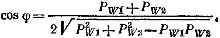
In a symmetrical three-phase circuit, the value of cosine phi can be determined from the readings of two wattmeters Pw1 and Pw2 by the formula
The total relative error of the considered methods is equal to the sum of the relative errors of each device; therefore, the accuracy of indirect methods is low.
The numerical value of cosine phi depends on the nature of the load.If the load is incandescent lamps and heating devices, then the cosine phi = 1, if the load also contains induction motors, then the cosine phi <1. When the load on the electric motor changes, its cosine phi changes significantly (from 0.1 at idle to 0.86 — 0.87 at nominal load), the cosine phi of the networks also changes.
Therefore, in practice, the so-called weighted average power factor for a certain time, for example, a day or a month. To do this, at the end of the considered period, readings are taken on the meters of active and reactive energy Wa and Wv, and the weighted average value of the power factor is determined by the formula
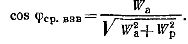
It is desirable that this value of the weighted average power factor in electrical networks should be equal to 0.92 - 0.95.
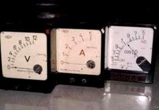
Using a phasor to measure power factor
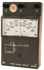
You can directly measure the phase shift between the load voltage and current using special measuring devices - phase meters.
The most common are phasometers of an electrodynamic system, in which the stationary coil is connected in series with the load, and the moving coils are connected in parallel with the load, so that the current of one of them lags behind the voltage β1 by a voltage. To do this, an active inductive load is connected in series with the coil, and the other current leads the voltage by a certain angle β2, for which an active-capacitive load is included, and β1 + β2 = 90О
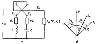
Rice. 1. Circuit diagram of the phase meter (a) and the vector diagram of voltages and currents (b).
The angle of deviation of the arrow of such a device depends only on the value of cosine phi.
 It is often used to measure the phase shift between two voltages digital phase meters... In direct conversion digital phase meters to measure the phase shift, it is converted to a time interval and the latter is measured. The investigated voltages are applied to two inputs of the device, on the digital device for reading the device, counting the number of pulses arriving at the counter of the device for one period of the investigated voltages, which corresponds to the phase shift in degrees (or parts of a degree) , are taken.
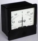
Of the panel instruments designed for measurement, the simplest phasometer of the D31 type, which can work in single-phase alternating current networks with a frequency of 50, 500, 1000, 2400, 8000 Hz. Accuracy class 2.5. The cosine phi measurement range is 0.5 to 1 capacitive phase shift and 1 to 0.5 inductive phase shift. Phase meters include via instrument current transformers with a secondary current of 5 A and measuring voltage transformers with a secondary voltage of 100 V.
To measure cosine phi in a three-phase network with a symmetrical load, panel phasors of type D301 can be used. Their accuracy class is 1.5. Series circuits are connected to a current of 5 A directly, as well as through a current transformer, parallel circuits are connected directly to 127, 220, 380 V, as well as through voltage measuring transformers.