Electric drive of lathes
 To get a profitable cutting speed on lathes, you need to have variations in the range of 80: 1 to 100: 1. In this case, it is desirable that the change is as smooth as possible to ensure the most favorable cutting speed in all cases.
The control range is called the ratio of the maximum angular speed (or rotation frequency) to the minimum, and for machines with translational motion, the ratio of the maximum to the minimum linear speed.
For a lathe group in which the main motion is rotary, it usually requires power constancy over most of the speed range, and only in the low speed range — moment constancy equal to the maximum allowable according to the main strength condition movement mechanism. Low rotation speeds are intended for specific types of processing: trimming, turning welded seams, etc.
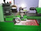
Lathe device:
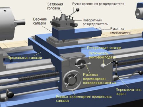
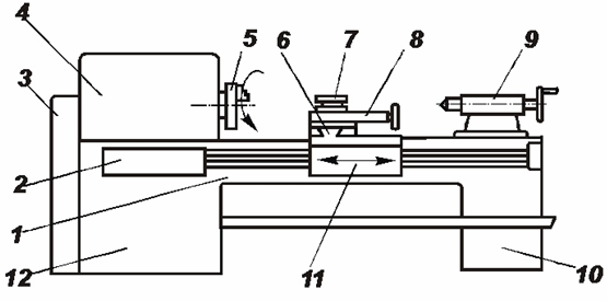 The main units of the lathe: 1 — bed; 2 — power supply box; 3 — guitar with replaceable gears; 4 — excavator with gearbox and spindle; 5-jaw self-centering chuck; 6 — longitudinal support; 7 — holder for tools; 8 — transverse carriage; 9 — tail; 10 — rear pedestal; 11 — apron; 12 — front pedestal Nodes and mechanisms of the screw-cutting lathe:
V main drives on lathes and drilling machines for a wide range of applications, small and medium, the main type of drive is an induction squirrel-cage motor.
Asynchronous engine structurally well combined with the gearbox of the machine, reliable in operation and does not require special maintenance.
On lathes with a constant spindle speed, with a change in the machining diameter drev, the cutting speed will change, m / min: vz = π x drev x nsp / 1000 Therefore, the machine spindle speed is determined by two factors — the diameter do6p and the cutting speed vz. The rational use of the machine requires a change in the speed of the spindle when the technological factors change.
For the most complete use of the cutting tool and the machine, the processing of the products should be carried out at the so-called economically viable (optimal) cutting speed, which, when the machine operates with an appropriate feed and depth of cut, should ensure the processing of the workpiece with the required accuracy and surface cleanliness at the lowest reduced unit machining costs, productivity will be slightly lower than the highest possible.
On small lathes, starting, stopping and reversing the direction of rotation of the spindle is often done using friction clutches. The motor remains connected to the mains and rotates in one direction.
For the main drive of some lathes, multi-speed asynchronous motors are used. The use of such a drive is recommended if it results in simplifying the gearbox or when it is necessary to switch the spindle speed on the fly. …
 Lathes for heavy duty and vertical lathes generally have an electromechanical stepless speed control of the main drive using a DC motor.
A relatively simple gearbox of such machines gives two to three steps of angular speed, and in the interval between two steps it is carried out in the range (3 — 5): 1 smooth adjustment of the angular speed of the motor by changing its magnetic flux speed. This, in particular, makes it possible to maintain a constant cutting speed when turning end and conical surfaces.
Smoothness of regulation is determined by the ratio of speeds in two adjacent control sections.The smoothness of the control significantly affects the performance of the machine, since the optimal cutting speed depends on the hardness of the material of the workpiece, the properties of the material and the geometry of the cutting tool, as well as on the nature of the processing. Parts of different sizes, different materials and different tools can be processed on the same machine, which is the reason for changing the cutting conditions.
Characteristic of the electric drive turning and drilling machines has a large moment of friction forces at the start of starting (up to 0.8 Mnom) and a significant moment of inertia of the face plate with a part exceeding the moment of inertia of the rotor of the electric motor by 8 — 9 times at high mechanical speeds. The use of a DC drive in this case provides a smooth start with constant acceleration.
In the shops of machine-building plants, there is usually no direct current network, therefore, to power the engines of heavy metal-cutting machines, separate converters are installed: electric machines (G -D system) or static (TP -D system).
Stepless electrical speed control (two-zone) is used in the automation of machines with a complex duty cycle, which makes it easy to readjust them to any cutting speed (for example, some automatic lathes for lathes).
A device for feeding small and medium-sized lathes is most often carried out by the main engine, which provides the possibility of threading. To adjust the feed rate, multi-stage feed boxes are used. Gears are shifted manually or using electromagnetic friction clutches (remotely).
Some modern lathes and boring machines use a separate DC drive with wide control for the feeder. The angular velocity of the motor varies in the range up to (100 — 200): 1 or more. Drive is carried out according to the EMU — D, PMU — D or TP — D system.
For auxiliary drives for lathes (accelerated movement of the carriage, product clamp, coolant pump, etc.), separate asynchronous squirrel-cage motors are used.
On. modern lathes, turning lathes and rotary machines are widely used to automate auxiliary movements as well as remotely control machine mechanisms.
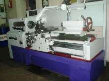
Electric drive of the screw-cutting lathe 1K62
The drive of the spindle and the working power supply of the support are carried out by an asynchronous squirrel-cage motor with a power of 10 kW. The angular speed of the spindle is controlled by switching the gears of the gearbox using the handles, changing the longitudinal and transverse feeds of the caliper. — shifting the gears of the gearbox also using the corresponding handles.
A separate 1.0 kW asynchronous motor is used for fast slide movements. Turning on and off the spindle of the machine, as well as its reversal, is carried out using a multi-layer friction clutch, which is controlled by two handles.The mechanical feed of the caliper in each direction is engaged with a single handle.
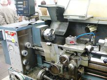
Turret lathe with electric drive 1P365
A feature of turning lathes is automatic speed switching and spindle feed without stopping the machine, which is carried out with the help of electromagnetic couplings built into the gearbox and feed box.
The spindle drive of the lathe lathe 1P365 is carried out by an asynchronous motor with a power of 14 kW, the second motor with a power of 1.7 kW drives the pump of the hydraulic system and is also used to achieve rapid longitudinal movement of two machine supports. The machine also has a cooling pump with a power of 0.125 kW.
The angular speed of the spindle is adjustable in steps from 3.4 to 150 rad / s. The movement of the gear units in the gearbox is carried out by hydraulic cylinders. The gearbox also contains a clutch consisting of two clutches: one to actuate the forward (right) rotation of the spindle and the other to actuate the reverse (left) rotation. The activation of these clutches is carried out by a hydraulic cylinder, whose pulley is accordingly translated with the help of electromagnets. Couplings connect the spindle motor shaft to the gearbox.
To stop the spindle quickly, a hydraulic brake is provided in the gearbox, which is controlled by a special hydraulic spool with the help of an electromagnet.
The supers are powered by the main drive. The feed rate is mechanically adjusted by switching gear blocks in the feed box using hydraulic cylinders.The setting of the required revolutions and feeds of the spindle is carried out with the help of the handles of the hydraulic switches located on the support aprons and acting on the hydraulic spool of the corresponding hydraulic cylinders.
All controls for the electric drives of the machine are located on the panel located on the front panel of the gearbox.
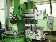
Model 1565 Boring Lathe Electric Drive
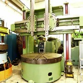 The face plate of the machine receives rotation from a DC motor (Pnom = 70 kW, Unom = 440 V, nnom = 500 rpm, nmax = 1500 rpm) through a V-belt transmission, a two-speed gearbox with manual shifting and a bevel gear.
The rotation speed of the face plate is controlled in the range of 0.4 to 20.7 rpm. The angular speed of the electric motor can be adjusted by changing the armature voltage in the range D = 5.7 and the excitation current in the range d =3. Feeder drive — from the main motor through the feed box — provides 12 feeds in the 0.2 to 16mm/rev range.
Thyristor electric drive lathe-carousel of the machine is a closed system for automatic speed stabilization with negative feedback, implemented using tachogenerator.
To reduce the face plate stop time in the turning lathe, an electric stop of the main drive is used. In this case, the polarity of the control voltage is changed and the motor is transferred to the generator operation mode.