Induction relays
 Induction relays are based on the interaction between a current induced in a wire and an alternating magnetic flux. Therefore, they only apply to alternating current as power system protection relay… As a rule, this is a secondary relay of indirect action.
Existing types of induction relays can be divided into three groups: frame relay, disk relay, glass relay.
In induction relays with a frame (Fig. 1, a), one of the flows (F2) induces a current in a short circuit placed in the form of a frame in the field of the second flow (F1), shifted in phase. The relays have high sensitivity and the fastest response compared to other inductive relays. Their disadvantage is low torque.
Disc induction relays are widely used. A diagram of the simplest relay of this type (with a short circuit K and a disk) is shown in fig. 1, b. Relays have a relatively simple design and a sufficiently large rotating moving part.
Induction relays with glass (Fig. 1, c) have a movable part in the form of glass, rotating in the magnetic field of two fluxes of a four-pole magnetic system.The fluxes F1 and F2 are located in space at an angle of 90 ° and shift with time at an angle γ.
A steel cylinder 1 passes inside the glass 5 to reduce the magnetic resistance. A glass relay is more complex than a disk relay, but allows a response time of up to 0.02 s. This significant advantage provides them with wide application.
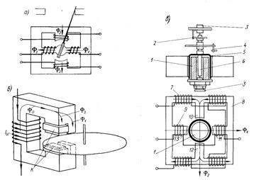
Rice. 1. Scheme of the device of induction relays: a — with a frame, b — with a disc, c — with glass: 1 — steel cylinder, 2 — helically opposed spring, 3 — bearings, 4 — auxiliary contacts, 5 — aluminum glass, 6 — axis, 7, 9 — coil groups, 8 — yoke, 10 — 13 — poles
The four-pole magnetic system makes it possible to obtain relays with different purposes without significant changes and to unify their production. For example, if the current coils 9 are placed on poles 11 and 13, and the voltage coils 7 are placed on the yoke, they will create fluxes F1 and F2, respectively, proportional to the current and voltage.
The interaction of these flows with currents induced in the glass 5 will create in the last torque M = k1F1F2 sin γ = k2IUcos φ, that is, we get a power relay.
With the same design, a frequency relay can be obtained if the voltage coils 9 are placed on poles 11 and 13 and connected in series with a resistor, and the coils 7 are connected in series with a capacitor. If both circuits (inductively active and inductively capacitive) are connected to the same voltage, then the moment created in glass 5 will be equal to M = k3fФ1Ф2 sin γ, where is — current frequency.
The inductance of the coils, the capacitance and the resistance are chosen so that at a given frequency setting the fluxes coincide in phase, that is, the angle is zero.When the frequency changes, the fluxes will not match in phase and the sign of their angle shift will depend on the nature of the frequency change. When the frequency increases or decreases, the glass turns in one direction or another and the closing (opening) of certain contacts.
Similarly, various combinations of core windings and other relays can be obtained for the purpose.
Combined current relays
The combined current relay has an inductive sensing element that operates with a time delay, depending on the current, and an electromagnetic sensing element with instantaneous action (interruption) that operates at high current values.
Current Overcurrent Induction Relays RT80
The frame rotates along the axes 3 and is held in the end position by the spring 2, i.e. spring against the limiter 1. A worm 18 is mounted on the axis of the disk. In the initial position of the frame, the segment 7, which has the teeth of the worm, is not engaged with the worm and the contacts 9 of the relay are open.
When the current flows through the relay coil Azp>Azcpp, the disk slowly starts to rotate under the influence of the electromagnetic moment created by the relay current. The frame rotates, the worm engages with the teeth of the segment and begins to gradually rise, overcoming the force of the spring 17 and closes the relay contacts with a special bus 10. The response time of the relay is adjusted from the initial position of the toothed segment using a screw , fixed to the time scale.
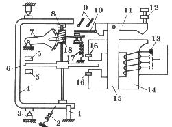
Rice. 2.RT-80 Series Maximum Current Induction Relay
The greater the current Azr in the coil of the electromagnet, the faster the disc will rotate and the shorter will be the time delay of the contacts. Operating current of the induction element AzCPR is adjusted when the number of turns of the coils changes (when the contact 13 is moved to the terminal block), Azcp> (2 — 10) A, response time 0.5 — 16 sec.
Overcurrent relays RT81, RT82, RT83, RT84, RT85, RT86 are used to protect electrical machines, transformers and transmission lines in case of short circuit and overload.
Relays of types PT83, PT84, PT86 are used in cases where overload signaling is required.
Relays of types PT81, PT82 have one main closing contact, acting immediately at short-circuit currents and with a time delay at overload in protected electrical installations. By rearranging the parts, the NO contact becomes an NC contact.
Relays of types PT83, PT84 have one main closing contact, acting immediately at short-circuit currents, and one closing signal contact, operating with a time delay at overload.
Relays of types RT85, RT86, intended for operation on auxiliary alternating current, have reinforced contacts for making and breaking with a common point, and the relay of type RT86, in addition to the main contacts, has a closing signal contact similar to the relay of type RT84. Reinforced make and break contacts in the PT85 type relay can act both instantaneously and with a time delay. In a PT86 type relay, these contacts can only operate momentarily.
RT90 Inductive Overcurrent Relays
Overcurrent relays RT91, RT95 are used to protect electrical installations from overload and short circuit.
The relays are made on the basis of the relays of the RT80 series and differ from them in the characteristic of the dependence of the time delay on the current.
The PT91 relays have one main closing contact acting immediately on short-circuit currents and with a time delay on overloads in protected electrical installations.
The RT95 relay has reinforced common-point make and break contacts and is designed to operate on auxiliary AC. Reinforced make and break contacts in the PT95 type relay can act both instantaneously and with a time delay.