Parameters and schemes of the rectifier
 Rectifier - a static device used to convert alternating current of a power source (mains) into direct current. The rectifier consists of a transformer, a valve group and a smoothing filter (Fig. 1).
The transformer Tr performs several functions: it changes the voltage of the network Uin to the value U1 required for correction, it electrically separates the load H from the network, it converts the number of phases of the alternating current.
The VG valve group is converted alternating current to pulsating one-way. The smoothing filter SF reduces the ripple of the rectified voltage (current) to the value acceptable for the load. The transformer Tr and the smoothing filter SF are optional elements of the rectifier circuit.
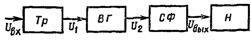
Rice. 1. Block diagram of the rectifier
The main parameters characterizing the quality of the rectifier's work are:
-
average values of rectified (output) voltage UWednesday and current AzWednesday,
-
ripple frequency is n output voltage (current),
-
ripple factor p, equal to the ratio of the amplitude of the wave voltage to the average value of the output voltage.Instead of a ripple factor p, the ripple factor for the first harmonic is often used, which is equal to the ratio of the amplitude of the first harmonic of the output voltage to its average value,
-
external characteristic — the dependence of the average value of the rectified voltage on the average value of the rectified current,
-
c. p. etc. η = Puseful / Pminuses = Puseful / (useful + Ptr + Pvg + Pf), where Ptr, Pvg, Pf — energy consumption in the transformer, in the group of valves and the smoothing filter.
 The operation of the rectifier (group of valves) is based on the properties of valves — non-linear two-terminal devices that pass current mainly in one (forward) direction.
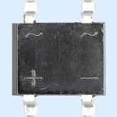
Semiconductor diodes are commonly used as valves. A valve with zero forward resistance and infinite reverse resistance is called ideal.
The current-voltage characteristics of real gates are close to V. a. NS. ideal valve. For operation in rectifiers, valves are selected according to operational parameters, which include:
-
highest (constant) operating current Az cmax - the maximum permissible average value of the corrected current flowing through the valve during its operation in a half-day resistive load circuit (under normal cooling conditions for a given valve and a temperature that does not exceed the limit value ),
-
maximum allowable reverse voltage (amplitude) Urevmax — reverse voltage that the valve can withstand for a long time. As a rule, the Urevmax voltage is equal to half the breakdown voltage,
-
forward voltage drop Upr — the average value of the forward voltage in half a rectifier circuit operating on a resistive load at rated current.
-
reverse current Iobr — the value of the current flowing through the valve when a permissible reverse voltage is applied to it,
-
maximum power Pmax — the maximum permissible power that can be dissipated by the valve.
Straightening chains
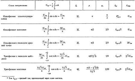
The most common rectification schemes are shown in figures., where the following designations are adopted: mc is the number of phases of the network voltage, m1 is the number of phases of the voltage at the input of the rectifier circuit (at the output of the transformer), m = fп / fc — coefficient equal to the ratio of the frequency of the output voltage waves to the frequency of the network voltage. Since the valves are shown everywhere semiconductor diodes.
The most common rectification and output voltage shape when operating on a resistive load:
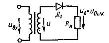
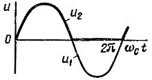
Single-phase half-wave rectifier circuit (mc = 1, m1 = 1, m = 1)
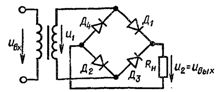
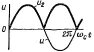
Single-phase full-wave rectifier circuit (bridge rectifier circuit mc = 1, m1 = 1, m =2)
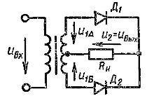
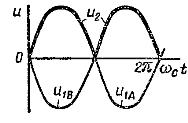
Single-phase rectifier circuit with midpoint output (mc = 1, m1 =2, m =2)
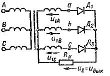
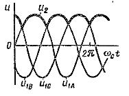
Three-phase rectification circuit with neutral output (mc =3, m1 =3, m =3)
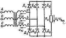
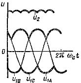
Three-phase bridge rectifier circuit (mc =3, m1 =3, m =6)
Basic relationships for rectifier circuits operating on a resistive load Rn under the assumption that the transformer and valves are ideal are given in the table: