Speed regulation of an induction motor
The most common are the following methods of controlling the speed of an asynchronous motor: a change in the additional resistance of the rotor circuit, a change in the voltage supplied to the stator winding, a change in the frequency of the supply voltage, as well as switching the number of poles.
Regulation of the speed of an induction motor by introducing resistors into the rotor circuit
Introduction resistors in the rotor circuit leads to an increase in power losses and a decrease in the speed of the motor rotor due to an increase in slip, since n = nО (1 — s).
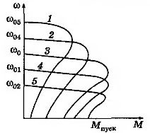
Fig. 1 it follows that as the resistance in the rotor circuit increases at the same torque, the engine speed decreases.
Hardness mechanical characteristics significantly decreases with decreasing rotation speed, which limits the control range to (2 — 3): 1. The disadvantage of this method is the significant energy losses, which are proportional to the slip. Such adjustment is possible only for rotor motor.
 Regulation of the rotation speed of an induction motor by changing the stator voltage
A change in the voltage applied to the stator winding of an asynchronous motor allows you to adjust the speed using relatively simple technical means and control schemes. To do this, a voltage regulator is connected between an alternating current network with a standard voltage U1nom and the stator of the electric motor.
When adjusting the speed asynchronous engine change in the voltage applied to the stator winding, the critical moment Mcr asynchronous motor varies in proportion to the square of the voltage applied to the motor Uret (Fig. 3) and the slip from Ureg does not depend.
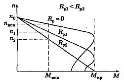
Rice. 1. Mechanical characteristics of an induction motor with a wound rotor at different resistances of resistors included in the rotor circuit
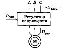
Rice. 2. Scheme for regulating the speed of an induction motor by changing the stator voltage
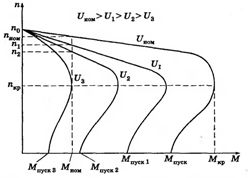
Rice. 3. Mechanical characteristics of an induction motor when changing the voltage applied to the stator windings
If the moment of resistance of the driven machine is greater starting torque of the electric motor (Ms> Mstart), then the motor will not rotate, so it is necessary to start it at the nominal voltage Unom or at idle.
It is thus possible to regulate the rotational speed of squirrel-cage induction motors with only a fan-like load. In addition, special high-slip motors must be used. The range of control is small, up to nkr.
To change the voltage, apply three-phase autotransformers and thyristor voltage regulators.
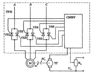
Rice. 4.Schematic of thyristor voltage regulator of closed-loop speed control system - induction motor (TRN - IM)
Closed-loop control of an asynchronous motor made according to the thyristor voltage regulator scheme — the electric motor allows you to adjust the speed of an asynchronous motor with increased slip (such motors are used in ventilation units).
Regulation of the speed of rotation of an induction motor by changing the frequency of the supply voltage
Since the rotation frequency of the stator magnetic field no = 60e/ p, then the adjustment of the rotation speed of the induction motor can be carried out by changing the frequency of the supply voltage.
 The principle of the frequency method for regulating the speed of an asynchronous motor lies in the fact that by changing the frequency of the supply voltage, in accordance with the expression with a constant number of pole pairs p, the angular speed can be changed by the magnetic field of the stator.
This method provides smooth speed control over a wide range, and the mechanical characteristics have high rigidity.
In order to obtain high energy performance of asynchronous motors (power coefficients, efficiency, overload capacity), it is necessary to change the supply voltage simultaneously with the frequency. The law of change of tension depends on the nature of the loading moment Ms. At constant torque load, the stator voltage must be controlled in proportion to the frequency.
A schematic diagram of a frequency electric drive is shown in fig. 5, and the mechanical characteristics of the frequency-tuned IM are shown in Fig. 6.
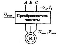
Rice. 5.Schematic of the frequency drive
Rice. 6. Mechanical characteristics of an asynchronous motor with frequency regulation
As the frequency f decreases, the critical moment slightly decreases in the region of low rotational speeds. This is due to an increase in the influence of the active resistance of the stator winding with a simultaneous decrease in frequency and voltage.
Frequency regulation asynchronous motor speed allows you to change the speed in the range (20 — 30): 1. The frequency method is the most promising for regulating an asynchronous motor with a rotor in a squirrel cage. Power losses with this arrangement are small because slip losses are minimal.
 The most modern frequency converters built according to the double conversion scheme. They consist of the following main parts: DC link (uncontrolled rectifier), pulse power inverter and control system.
The DC link consists of an uncontrolled rectifier and a filter. The alternating voltage of the supply network is converted into a direct current voltage.
The power three-phase pulse inverter contains six transistor switches. Each motor winding is connected through its corresponding switch to the positive and negative terminals of the rectifier. The inverter converts the rectified voltage into a three-phase alternating voltage of the desired frequency and amplitude, which is applied to the stator windings of the electric motor.
In the output stages of the inverter, power switches are used as switches. IGBT transistors… Compared to thyristors, they have a higher switching frequency, which allows them to produce a sinusoidal output signal with minimal distortion.Regulation of the output frequency The downstream and output voltages are realized by high-frequency pulse width modulation.
Controlling the switching speed of an induction motor Pole pair
Stepped speed control can be performed using special squirrel cage multispeed induction motors.
From the expression no = 60e/ p it follows that when the number of pole pairs p changes, mechanical characteristics with different rotation speeds are obtained for the magnetic field of the stator. Since the value of p is determined by integers, the transition from one characteristic to another in the adjustment process is stepwise.
There are two ways to change the number of pole pairs. In the first case, two windings with different numbers of poles are placed in the slots of the stator. When the speed changes, one of the windings is connected to the network. In the second case, the winding of each phase consists of two parts that are connected in parallel or in series. In this case, the number of pole pairs changes by a factor of two.
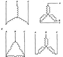
Rice. 7. Schemes for switching the windings of an asynchronous motor: a — from a single star to a double star; b — from a triangle to a double star
Speed control by changing the number of pole pairs is economical, and the mechanical characteristics maintain rigidity. The disadvantage of this method is the step-like nature of the change in speed of the squirrel-cage rotor induction motor. Two speed motors are available with 4/2, 8/4, 12/6 poles. The 12/8/6/4 pole four-speed electric motor has two switching windings.
Materials used from the book Daineko V.A., Kovalinsky A.I. Electrical equipment of agricultural enterprises.