What is inductance
 Inductance is called an idealized element of an electric circuit in which the energy of a magnetic field is stored. The storage of electric field energy or the conversion of electric energy into other types of energy does not occur in it.
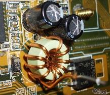
The closest thing to an idealized element — the inductance — is a real element of an electric circuit — inductive coil.
Unlike an inductance, an inductance coil also stores the energy of the electric field and converts the electric energy into other types of energy, specifically heat.
Quantitatively, the ability of real and idealized elements of an electric circuit to store the energy of a magnetic field is characterized by a parameter called inductance.
Thus, the term "inductance" is used as the name of an idealized element of an electrical circuit, as the name of a parameter that quantitatively characterizes the properties of this element, and as the name of the main parameter of an inductive coil.
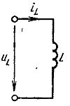
Rice. 1. Conventional graphical notation of inductance
The relationship between voltage and current in an inductive coil is determined the law of electromagnetic induction, from which it follows that when the magnetic flux penetrating the inductive coil changes, an electromotive force e is induced in it, proportional to the rate of change of the flux linkage of the coil ψ and directed in such a way that the current caused by it , tends to prevent a change in the magnetic flux:
e = — dψ / dt
The flux linkage of the coil is equal to the algebraic sum of the magnetic fluxes penetrating its individual turns:
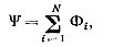
where N is the number of coil turns.
A magnetic flux F penetrating each of the turns of the coil, in the general case, may contain two components: the magnetic flux for self-induction Fsi and the magnetic flux of external fields Fvp: F — Fsi + Fvp.
The first component is the magnetic flux caused by the current flowing through the coil, the second is determined by magnetic fields whose existence is unrelated to the current in the coil — the Earth's magnetic field, the magnetic fields of other coils and permanent magnets… If the second component of the magnetic flux is caused by the magnetic field of another coil, then it is called the magnetic flux of mutual induction.
Coil flux ψ, as well as magnetic flux Φ, can be represented as a sum of two components: self-induction flux linkage ψsi and external field flux linkage ψvp
ψ= ψsi + ψvp
e = esi + dvp,
here eu is the EMF of self-induction, evp is the EMF of external fields.
If the magnetic fluxes of the fields external to the inductive coil are equal to zero and only the self-induced flux penetrates the coil, then only EMF of self-induction.
The inductance flux relationship depends on the current flowing through the coil. This dependence, called Weber - the ampere characteristic of the inductive coil, generally has a non-linear character (Fig. 2, curve 1).
In a particular case, for example, for a coil without a magnetic core, this dependence can be linear (Fig. 2, curve 2).
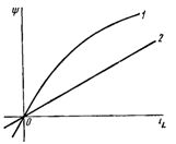
Rice. 2. Characteristics of the Weber-ampere of the inductive coil: 1 — non-linear, 2 — linear.
In SI units, inductance is expressed in henries (H).
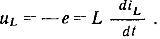
When analyzing circuits, the value of the EMF induced in the coil is usually not taken into account, but the voltage at its terminals, the positive direction of which is chosen to coincide with the positive direction of the current:
An idealized element of an electrical circuit — inductance — can be seen as a simplified model of an inductive coil, reflecting the coil's ability to store the energy of a magnetic field.
For a linear inductance, the voltage across its terminals is proportional to the rate of change of the current. When direct current flows through the inductance, the voltage across its terminals is zero, hence the resistance of the inductance to direct current is zero.