Stepper motors
 A stepper motor is an electromechanical device that converts electrical signals into discrete angular motions of a shaft. The use of stepper motors allows the working bodies of the machines to perform strictly dosed movements by fixing their position at the end of the movement.
Stepper motors are actuators that provide fixed angular movements (steps). Any change in rotor angle is the stepper motor's response to the input pulse.
A discrete electric stepper motor drive is naturally combined with digital control devices, which allows it to be successfully used in digitally controlled metal cutting machines, in industrial robots and manipulators, in clock mechanisms.
A discrete electric drive can also be implemented using a series asynchronous electric motors, which due to special control can work in step mode.
The principle of operation of stepper motors of all types is as follows. With the help of an electronic switch, voltage pulses are generated, which are fed to the control coils located on the stator of the stepper motor.
Depending on the sequence of excitation of the control coils, one or another discrete change in the magnetic field occurs in the operating gap of the motor. With the angular displacement of the axis of the magnetic field of the control coils of the stepper motor, its rotor discretely rotates following the magnetic field. The law of rotation of the rotor is determined by the sequence, duty cycle and frequency of the control pulses, as well as by the type and design parameters of the stepper motor.
The principle of operation of a stepper motor (obtaining discrete movement of the rotor) will be considered using the example of the simplest circuit of a two-phase stepper motor (Fig. 1).
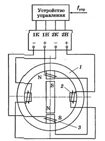
Rice. 1. Simplified diagram of a stepper motor with an active rotor
The stepper motor has two pairs of clearly defined stator poles on which the excitation (control) windings are located: winding 3 with terminals 1H — 1K and winding 2 with terminals 2H — 2K. Each winding consists of two parts located at opposite poles of the stator 1 SM.
The rotor in the considered scheme is a two-pole permanent magnet.The coils are powered by pulses from a control device that converts a single-channel sequence of input control pulses into a multi-channel one (according to the number of phases of the stepper motor).
The position will be stable because there is a synchronizing moment acting on the rotor which tends to return the rotor to the equilibrium position: M = Mmax x sinα,
where M.max — the maximum moment, α — the angle between the axes of the stator and rotor magnetic fields.
When the control unit switches the voltage from coil 3 to coil 2, a magnetic field with horizontal poles is generated, i.e. the stator magnetic field makes a discrete rotation with a quarter of the stator circumference. In this case, an angle of divergence between the axes of the stator and the rotor α = 90 ° will appear and the maximum torque Mmax will act on the rotor. The rotor will rotate through an angle α = 90 ° and take a new stable position. Thus, after the stepping motion of the stator field, the rotor of the motor moves stepwise.
The stepper motor is started by a sudden or gradual increase in the frequency of the input signal from zero to the operating one, the stop is by decreasing the zero, and the reverse is by changing the switching sequence of the windings of the stepper motor.
Stepper motors are characterized by the following parameters: the number of phases (control coils) and their connection scheme, the type of stepper motor (with active or passive rotor), single rotor step (the angle of rotation of the rotor with a single pulse), nominal power supply voltage, maximum static time moment, rated torque, rotor moment of inertia, acceleration frequency.
Stepper motors are single-phase, two-phase and multiphase with an active or passive rotor. The stepper motor is controlled by an electronic control unit. An example of a stepper motor control scheme is shown in Figure 2.
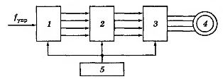
Rice. 2. Functional diagram of an open-loop stepper motor electric drive
A control signal in the form of voltage pulses is supplied to the input of block 1, which converts the sequence of pulses, for example, into a four-phase system of unipolar pulses (in accordance with the number of phases of the stepper motor).
Block 2 generates these pulses with respect to the duration and amplitude necessary for the normal operation of the switch 3, to the outputs of which the windings of the stepper motor 4 are connected. The switch and the other blocks are powered by a direct current source 5.
With increased requirements for the quality of a discrete drive, a closed circuit of a stepper electric drive (Fig. 3) is used, which, in addition to a stepper motor, includes a converter P, a commutator K and a step sensor DSh. In such a discrete drive, information about the actual position of the shaft of the working mechanism RM and the speed of the stepper motor is fed to the input of the automatic regulator, which provides the set nature of the movement of the drive.
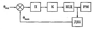
Rice. 3. Functional diagram of a closed-loop discrete drive
Modern discrete drive systems use microprocessor controls. The range of applications for stepper motor drives is constantly expanding. Their use is promising in welding machines, synchronizing devices, tape and recording mechanisms, fuel supply control systems for internal combustion engines.
The advantages of stepper motors:
-
high accuracy, even with an open-loop structure, i.e. without steering angle sensor;
-
native integration with digital management applications;
-
lack of mechanical switches that often cause problems with other types of engines.
Disadvantages of stepper motors:
-
low torque, but compared to continuous drive motors;
-
limited speed;
-
high level of vibration due to jerky movement;
-
large errors and oscillations with loss of pulses in open-loop systems.
The advantages of stepper motors far outweigh their disadvantages, so they are often used in cases where the small power of the drive devices is sufficient.
The article uses materials from the book Daineko V.A., Kovalinsky A.I. Electrical equipment of agricultural enterprises.