Faucet protection panels
 The tap protection buttons are designed for overcurrent protection (in case of short circuit and overload), zero protection (in case of unacceptable narrowing or loss of voltage), limit protection (in combination with limit switches) and zero blocking - prohibition of starting electric motors if at least one of power controllers or the controller is not in zero position.
In addition, with the help of protective panels, the crane installations are switched off when the emergency switch and hatch contact are opened.
The protective panels of the crane are not used for those types of magnetic controllers that have their own types of protection, for example, for magnetic controllers TAZ-160, K-63, K-160, K-250.
Install on the faucet protection panel: line contactor (one or more), overcurrent relay, switch and control circuit fuses.
The most widely used are domestically produced crane protection panels of the PZKB-160 and PZKB-400 types - for cranes receiving power from the electrical network, and of the PPZB-160 type - for cranes charging from the DC network.
The protective panels of the PZKB-400 crane differ from the PZKB-160 panels in the value of the total current of the electric motors.
Depending on the number of electromagnetic elements of the overcurrent relay and the circuit for their switching, there are different options for turning on the power circuits of the PZKB-160 and PZKB-400 protective panels.
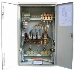
Re. 1. Protective panel of crane PKZB-160
The protection panel currents are selected according to the nature of the current, the network voltage, the sum of the nominal currents of the electric motors and the type of control.
When choosing a circuit for switching on the power circuits of the panels and the limit of adjustment of the electromagnetic elements of the overcurrent relay, the cross-section of the branch wires to each electric motor is selected in advance for heating. To do this, you can use the following data:
Section, mm2 2.5 4 6 10 16 25 35 50 Long-term permissible current, A 22 31 37 55 70 90 110 150 Current at PV up to 40 A 22 31 37 76 97 125 152 207
A circuit option is then selected to turn on the power circuits of the protection panel based on the following.
To protect the electric motor from overload, it is sufficient to have an electromagnetic element of the overcurrent relay in one phase of each electric motor. In order to protect the network, electromagnetic elements common to several electric motors are installed in the remaining two phases.
The setting current of the common electromagnetic elements of the relay is found by the formula Aztotal = 2.5Azd + Azp1 + Azp2,
where Azd — operating current of the protected electric motor, highest in power, Azp1 and Az p2 — operating currents of the remaining electric motors from among the protected by common electromagnetic elements.
Relays for individual electric motors are selected according to their power and voltage and set to a tripping current equal to 2.5 times the rated current of the rated load at duty cycle = 40%.
It should be noted that installing separate protection for each phase is not always beneficial. Therefore, for example, with a short network length, it is advisable to increase the cross-section of the drive or network cable, instead of installing an additional electromagnetic element of the overcurrent relay.
Increasing the cross-section is also recommended in cases where the use of separate protection of electric motors leads to an increase in the number of trolleys or collector rings.
If a protective panel of the PZKB-160 type is suitable for the current, but there are more electromagnetic elements of the overcurrent relay in the selected scheme, then it is recommended to adopt one of the schemes of this panel and increase the cross-section of the corresponding wires or cables, if this increase is relatively small.
The general electromagnetic elements of the relay are selected in accordance with the calculated current for the selected protection scheme. If Aztotal is within two relays, then the relay is selected for the higher allowable current.
In fig.2 shows a diagram of the control circuits of the protective panels PZKB-160 and PZKB-400 in the case of using cam and magnetic controllers. Button SB designed to supply voltage to the linear winding and contactor KM after setting all controllers to the zero position.
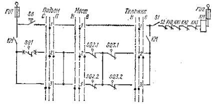
Rice. 2. Scheme of control circuits of protective panels PZKB -160 and PZKB -400, KM — linear contactor, SB — button for switching on the contactor KM, S1 — emergency switch, S2 — roof contact, SQ1 — limit switch contact for lifting, SQ2.1 and SQ2 .2 — the contacts of the limit switches of the bogie when moving respectively "forward" (B) and "backward" (H), SQ3.1 and SQ3.2 — the same as for the bridge, KA0, KA1, KA2, KAZ — contacts of the maximum current of the relay, FU1, FU2 — fuses.
In fig. 3 shows a diagram of the protective panel PPZB-160. Maximum protection in this circuit is provided by four-pole overcurrent relays (with four electromagnetic elements).
Separate coils of the relay KA1 — KAZ are switched on from the side of one of the poles in the circuit of each electric motor, and on the other pole, the coil KAO common to all electric motors is switched on, which protects the crane network.
The PPZB-160 crane protection panel is designed to protect three DC motors and is available in 220 and 440 V versions.
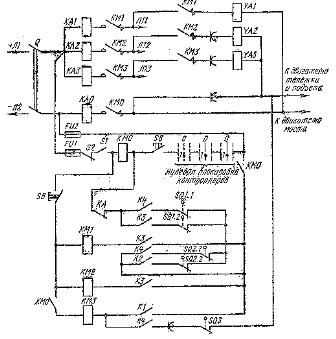
Re.3... Scheme of PPZ protective panelB-160: Q1 — rubkaiteilnik, YAZ, YA2, YAZ — braking electromagnetic coils KM1, KM2, KMZ, KMO — respectively contactors for controlling the electric motors of the bridge, trolley, lifting and general, KA1, KA2, KA3, KA — overcurrent relay, SQ1.1 and bridge limit switch contacts, SQ2.1 and SQ2.2 — the same, but these filters lie, SQ3 — the same, but lifting, S1 — emergency switch, S2 — hatch contact, K1, K2, KZ, K4 — contacts of the controller.
When the controllers are moved or by command of the controllers to the zero position, the contactor of the corresponding mechanism KM1 is turned off, KM2, KM3, when the limit switches of the bridge or trolley mechanisms are actuated, as well as in case of overload, the contactors KMO, KM1, KM2 are excluded, KM3.
NC contact button SB turns off the simultaneous supply of voltage to the coils of contactor KM0 and contactors KM1, KM2, KMZ to avoid their inclusion during a short circuit in the network. The K1 contacts of the controllers prevent the possibility of turning on the crane motors in cases where at least one of the controllers (or command controllers) is not in the zero position.