The device and parameters of thyristors
 A thyristor is a semiconductor device with three (or more) p-n junctions, the current-voltage characteristic of which has a negative differential resistance section and which is used for switching in electrical circuits.
The simplest thyristor with two outputs is a diode thyristor (dynistor). The triode thyristor (SCR) additionally has a third (control) electrode. Both diode and triode thyristors have a four-layer structure with three p–n junctions (Fig. 1).
The end areas p1 and n2 are called anode and cathode respectively, a control electrode is connected to one of the middle areas p2 or n1. P1, P2, P3- transitions between p- and n-regions.
A source E of the external supply voltage is connected to the anode with a positive pole relative to the cathode. If the current Iу through the control electrode of the triode thyristor is zero, its operation does not differ from the operation of the diode. In some cases, it is convenient to represent the thyristor as a circuit equivalent to two transistors, using transistors with different types of electrical conductivity p-n-p and n-R-n (Fig. 1, b).
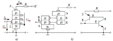
Fig. 1.Structure (a) and two-transistor equivalent circuit (b) of a triode thyristor
As can be seen from fig. 1, b, transition P2 is a common collector transition of the two transistors in the equivalent circuit, and transitions P1 and P3 are emitter junctions. As the forward voltage Upr increases (which is achieved by increasing the emf of the power source E), the thyristor current increases slightly until the voltage Upr approaches a certain critical value of the breakdown voltage, equal to the turn-on voltage Uin (Fig. 2).
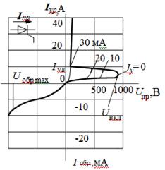
Rice. 2. Current-voltage characteristics and conventional designation of a triode thyristor
With a further increase in the voltage Upr under the influence of an increasing electric field in the P2 transition, a sharp increase in the number of charge carriers formed as a result of impact ionization during the collision of charge carriers with atoms is observed. As a result, the junction current rapidly increases as electrons from the n2 layer and holes from the p1 layer rush into the p2 and n1 layers and saturate them with minority charge carriers. With a further increase in the EMF of the source E or a decrease in the resistance of the resistor R, the current in the device increases in accordance with the vertical section of the I — V characteristic (Fig. 2)
The minimum forward current at which the thyristor remains on is called the holding current Isp. When the forward current decreases to the value Ipr <Isp (descending branch of the I — V characteristic in Fig. 2), the high resistance of the connection is restored and the thyristor turns off. The resistance recovery time of the p — n junction is typically 1 — 100 µs.
The voltage Uin at which an avalanche-like current increase begins can be reduced by further introducing minority charge carriers into each of the layers adjacent to the P2 junction. These additional charge carriers increase the number of ionization actions in the P2 p-n junction and therefore the turn-on voltage Uincl decreases.
Additional charge carriers in the triode thyristor shown in Fig. 1, are introduced into the p2 layer by an auxiliary circuit powered by an independent voltage source. The extent to which the turn-on voltage decreases as the control current increases is shown by the family of curves in Fig. 2.
Transferring to the open (on) state, the thyristor does not turn off even when the control current Iy decreases to zero. The thyristor can be turned off either by lowering the external voltage to a certain minimum value, at which the current becomes less than the holding current, or by supplying a negative current pulse to the circuit of the control electrode, the value of which, however, is commensurate with the value of the forward switch current Ipr.
An important parameter of the triode thyristor is the unlocking control current Iu on — the current of the control electrode, which ensures the switching of the thyristor in the open state. The value of this current reaches several hundred milliamperes.
Fig. 2 it can be seen that when a reverse voltage is applied to the thyristor, a small current occurs in it, since in this case the transitions P1 and P3 are closed. To avoid thyristor damage in the reverse direction (which puts the thyristor out of operation due to thermal breakdown of the stroke), the reverse voltage is required to be less than Urev.max.
In symmetrical diode and triode thyristors, the inverse I — V characteristic coincides with the forward one. This is achieved by anti-parallel connection of two identical four-layer structures or by using special five-layer structures with four p-n junctions.
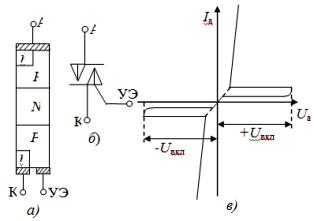 Rice. 3. The structure of a symmetrical thyristor (a), its schematic representation (b) and the current-voltage characteristic (c)
Currently, thyristors are produced for currents up to 3000 A and turn-on voltages up to 6000 V.
The main disadvantages of most thyristors are incomplete controllability (the thyristor does not turn off after removing the control signal) and relatively low speed (tens of microseconds). Recently, however, thyristors have been created in which the first drawback has been removed (locking thyristors can be turned off using the control current).
Potapov L.A.