Electric drive of electric hoists and crane beams
 Suspended electric trolleys (electrified hoists, hoists and crane beams) are used to lift and move loads and machine parts during assembly and repair work in industrial premises. Electric hoists, hoists and cranes are smaller than bridge cranes, which reduces the size of industrial buildings and their maintenance does not require qualified personnel.
Suspended electric trolleys are designed for lifting and moving goods in production facilities along a strictly defined path.
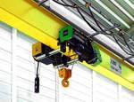
An electric truck (Fig. 1) consists of 3 main parts: a lifting mechanism (electric hoist) designed to lift (lower) and hold the load, a movement mechanism (undercarriage) designed to move the lifted load to a strictly defined position direction, a monorail that defines horizontal movement in two directions.
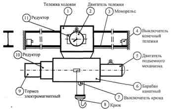
Rice. 1. Kinematic diagram of the suspended electric carriage
The electric hoist is mounted on a working trolley and includes the following equipment: electric motor (5) of the lifting mechanism, cylindrical gearbox (10) for reducing the speed of rotation of the electric motor to a value that provides a given linear speed of lifting (lowering) the hook, electromagnetic brake (9), to stop the motor of the shaft when it is disconnected from the mains or the voltage disappears in the network, a braking brake is activated, acting on the force of the springs, when the shafts are wrapped around the shaft, the limit switch (7) of the hook, to limit the lifting of the hook, when pressed, the engine is disconnected from the network and slows down, the rope drum (6), for winding (unwinding) and storing the rope, the hook (8), for securing the lifted load .
The undercarriage is mounted on the monorail (3), supported by the running wheels on the lower flanges of the double rail. Driving the wheels through a cylindrical gearbox (11) by an electric motor (2).
Monorail — I -beam with limit switches (4) at ends to limit horizontal movement.
Electric hoist TEP-1 (load capacity 1 t, voltage 380 V) consists of lifting and moving mechanisms with individual electric drives. The working drum 2 is driven by the engine 20 through a planetary gearbox consisting of satellites 5, 7, 8, block gears 13, sun gears 6, 9, carrier 14, 15. The main drive shaft 4 when the engine is off is stopped by discs 10 under the action of spring 11.
To drive the lifting mechanism at a speed of 6.5-6.9 m / s, an asynchronous motor with increased slip of the AOS-32-4M type is used (power 1.4 kW at 1320 rpm and duty cycle = 25%).The upward movement of the hook is limited by a limit switch.
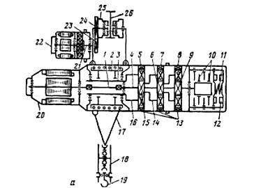
Rice. 2. Electric drive of electric hoist TEP -1: 1 — working drum, 3 — hollow shaft, 4 — working shaft, 5, 7, 8 — satellites, 6, 9, 15 — sun gears, 10 — brake discs, 11 — brake spring, 12 — electromagnets, 13 — block gears, 14, 16, 21 — carriers, 17 — cable, 18 — suspension, 19 — hook, 20 — electric motor for lifting the load, 22 — trolley electric motor, 23, 24 — gears, 25 — roller, 26 — monorail.
Figure 3 shows the operation of the hoist. The efficiency of the electric hoist increases to 0.58 as the mass of the lifted load increases to 1000 kg.
Interesting mode of operation of motor 4 when lowering the load: while the weight of the load is less than 425 kg, the electric motor works in motor mode, and when the mass is over 425 kg — in generator mode. Therefore, to overcome the idle moment of the lifting mechanism, a load weighing 425 kg is sufficient.
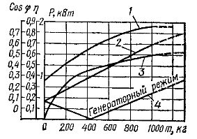
Rice. 3. Operating characteristics of an electric hoist: 1 — ssphi of the electric motor, 2 — the power of the electric motor when lifting the load, 3 — efficiency, 4 — the power of the electric motor when lowering the load.
To drive the undercarriage of the electric hoist, an asynchronous electric motor 22 (Fig. 2) of the TEM-0.25 type (power 0.25 kW at 1410 rpm and duty cycle = 25%) with a built-in planetary single-stage gearbox and gear 23, 24, transmitting rotation of rollers 25. Braking devices are not mounted on the movement mechanisms of the simplest hoists. The movement of the hoist along the beam in both directions is limited by mechanical stops.
 A jib crane differs from a hoist in that the beam on which the hoist travels can move around the production room, driven by a squirrel-cage or phase rotor electric motor. The crane beam bridge, which has an electric drive mechanism, is made in the form of a single beam on which the electric undercarriage moves.
Three-phase asynchronous motors with a squirrel-cage rotor are used to drive outboard electric cars and only with a high load capacity and the need for speed regulation and smooth "landing" of loads-asynchronous motors with a phase rotor.
Due to the lack of low speed necessary for smooth landing of loads or accurate stopping of the crane, the worker must periodically turn on and off the electric motors, and this increases the number of starts and causes heating of the windings, and also reduces the wear resistance of the contacts. Therefore, on some cranes there are electric drives for lifting and traveling with two operating speeds: nominal and reduced, which are provided by using two-speed asynchronous motors instead of single-speed or an additional micro drive.
 Low-speed (0.2 — 0.5 m / s) suspended electric trolleys powered by squirrel-cage motors are usually controlled from floor (ground) level using suspended push button stations… In air trolleys and cranes with a cabin for the operator (at a speed of 0.8 — 1.5 m / s), the motors with a phase rotor are controlled by controllers.
The electric motors of the hoists and overhead cranes are controlled by reversible magnetic starters and start buttons suspended from a flexible armored cable.The voltage to the coils and contacts of the contactors for raising KM1 (Fig. 4), lowering KM2, moving KMZ forward and backward KM4 is supplied through a circuit breaker and a cable or contact wires. The upward movement of the lifting device is limited by a limit switch. SQ.
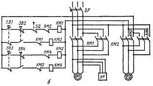
Rice. 4. Electric schematic diagram of the crane-beam
Blocking of reversing contactors of motors from simultaneous switching on is carried out by means of double circuit buttons and mechanical blocking of the contactors themselves (or opening of auxiliary contacts of contactors).
On electric hoists and overhead cranes, the start buttons are not bypassed by the corresponding closing contactor interlock contacts, preventing the hoist from continuing to operate after the operator releases the push button pendant station. At the same time as the lifting motor, the UA solenoid is actuated, which opens the brake.
The maximum permissible starting time for lifting mechanisms is 3 — 5 s, for movement mechanisms — 10 — 15 s.
You can also see: Electrical equipment and chains of electric hoists
The mode of operation of the engines of electric trucks, electric hoists and overhead cranes depends on their purpose. If the goods are moved on bridge cranes over short distances, then the engines work in a shameful short-term mode (for example, in trolleys serving sections of workshops or warehouses).
For overhead cranes transporting goods across the territory of the plant over relatively large distances, the operating modes of the lifting and moving motors are different: the first is characterized by a short-term mode, the second by a long-term one. The power of the motors for lifting and moving electric hoists, hoists and gantry cranes is determined in the same way as for engines of overhead crane mechanisms.