How to reduce the rectified voltage ripple
 The voltage received by the rectifiers is not constant, but pulsating. It consists of constant and variable components. The larger the variable component with respect to the constant, the greater the disturbance and the worse the quality of the rectified voltage.
The variable component is formed by harmonics. The harmonic frequencies are defined by the equality
f (n) =kmf,
where k is the harmonic number, k = 1, 2, 3,…, m is the number of pulses of the rectified voltage, f is the frequency of the mains voltage.
The quality of the rectified voltage ripple coefficient p is evaluated, which depends on the average value of the rectified voltage and the amplitude of the fundamental harmonic in the load.
The order of the harmonic components n = km contained in the rectified voltage curve depends only on the number of pulses and does not depend on the specific rectifier circuits... The harmonics of the lowest numbers have the highest amplitude.
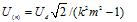
The effective voltage value of the harmonic component of the order of n depends on the average value of the rectified voltage Ud of an ideal unregulated rectifier:
In real circuits, the current transition from one diode to another takes place within a certain finite period of time, measured in fractions period of alternating tension and called a switching angle... The presence of switching angles greatly increases the amplitude of harmonics. As a result, you grow rectified wave excitement.
The AC component of the rectified voltage, consisting of low and high frequency harmonics, creates an AC current in the load that interferes with other electronic devices.
To reduce the ripple of the rectified voltage between the output terminals of the rectifier and the load include a smoothing filter, which significantly reduces the ripple of the rectified voltage by suppressing harmonics.
The main elements of smoothing filters are inductors (throttles) and capacitors, and at low powers and transistors.
The operation of passive filters (without transistors and other amplifiers) is based on the frequency dependence of the resistance value of the reactive elements (inductor and capacitor). Inductor resistance Xl and capacitor X° C: Xl = 2πfL, X° C = 1 / 2πfC,
where f is the frequency of the current flowing through the reactive element, L is the inductance of the choke, C is the capacitance of the capacitor.
From the formulas for the resistance of the reactive elements, it follows that with an increase in the frequency of the current, the resistance of the coil inductance (choke) increases and the capacitor decreases. For direct current, the resistance of the capacitor is infinite and the inductor is zero.
This feature allows the inductor to freely pass the DC component of the rectified current and delay harmonics.Also, the higher the harmonic number (the higher its frequency), the more effectively it slows down. On the contrary, the capacitor completely blocks the DC component of the current and passes harmonics.
The main parameter characterizing the effectiveness of the filter is the smoothing (filtering) coefficient
q = p1 / p2,
where p1 is the ripple factor of the rectifier output in a circuit without a filter, p2 is the ripple factor of the filter output.
In practice, passive L-shaped, U-shaped and resonant filters are used. The most widely used are L-shaped and U-shaped, the diagrams of which are shown in Figure 1
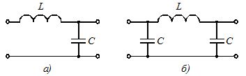
Figure 1. Schematics of passively smoothing L-shaped (a) and U-shaped (b) filters to reduce rectified voltage ripple
The initial data for calculating the inductance of the filter choke L and the capacitance of the filter capacitor C are the ripple factor of the rectifier, circuit variant and the required ripple factor of the filter output.
The calculation of the filter parameters begins with the determination of the smoothing coefficient. Then you need to randomly choose the filter circuit and the capacitance of the capacitor in it. The capacitance of the filter capacitor is selected from the capacitance range given below.
In practice, capacitors with the following capacities are used: 50, 100, 200, 500, 1000, 2000, 4000 uF. It is recommended to use smaller capacitance values of this series at high operating voltages and large capacitances at low voltages.
The choke inductance in the L-shaped filter circuit can be determined from the approximate expression

for a U-shaped scheme —

In the formulas, the capacitance is substituted in microfarads, and the result is obtained in henries.
Voltage Rectified Ripple Voltage Filtering