Transformer operating modes
 Depending on the value of the load, the transformer can operate in three modes:
1. Idle operation at load resistance zn = ∞.
2. Short circuit at zn = 0.
3. Charging mode at 0 <zn <∞.
Having the parameters of the equivalent circuit, you can analyze any operating mode of the transformer... The parameters themselves are determined based on no-load and short-circuit experiments. At idle, the secondary winding of the transformer is open.
A no-load transformer test is carried out to determine the transformation ratio, the power losses in the steel and the parameters of the magnetizing branch of the equivalent circuit, usually carried out at the rated voltage of the primary winding.
For single phase transformer based on the data from the idle test it is possible to calculate:
— transformation factor
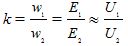
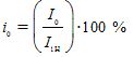
— percentage of no-load current
Is the active resistance of the branch magnetization r0 determined by the condition
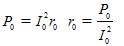
— total resistance of the magnetizing branch

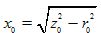
— inductive resistance of the magnetizing branch
The idle power factor is also often defined as:
In some cases, the no-load test is carried out for several values of the primary winding voltage: from U1 ≈ 0.3U1n to U1 ≈ 1.1U1n. Based on the obtained data, the idle characteristics are drawn, which are the dependence of P0, z0, r0 and cosφ as a function of the voltage U1. Using the no-load characteristics, it is possible to set the values of the specified quantities at any value of the voltage U1.
To determine the short-circuit voltage, the losses in the windings and the resistances rk and xk are tested in a short circuit. In this case, such a reduced voltage is applied to the primary winding so that the currents of the short-circuited transformer windings are equal to their nominal values, i.e. I1k = I1n, I2k = I2n. The voltage of the primary winding, at which the specified conditions are met, is called the nominal short-circuit voltage Ukn.
Given that Ucn is usually only 5-10% of U1n, the mutual induction flux of the transformer core during the short-circuit test is tens of times smaller than in the nominal mode, and the transformer steel is unsaturated. Therefore, the losses in the steel are neglected and it is considered that all the power Pcn supplied to the primary winding is spent on heating the windings and determines the value of the active short-circuit resistance rc.
During the experiment, the voltage Ukn, the current I1k = I1n and the power Pkn of the primary coil are measured. Based on this data, you can determine:
— percentage of short-circuit voltage
— active short-circuit resistance

— active resistances of the primary and reduced secondary windings, approximately equal to half the short-circuit resistance

— short circuit impedance

— short-circuit inductive resistance

— inductive resistance of the primary and reduced secondary winding, approximately equal to half of the short-circuit inductive resistance

— resistance of the secondary winding of a real transformer:
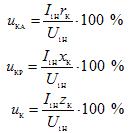
— inductive, active and total percentage short-circuit voltage:
V load mode it is very important to know how the load parameters affect the efficiency and voltage variation at the terminals of the secondary winding.
Transformer efficiency is the ratio of active power delivered to the load to active power supplied to the transformer.
The efficiency of the transformer is of great importance. For low-power power transformers, it is approximately 0.95, and for transformers with a capacity of several tens of thousands of kilovolt-amperes, it reaches 0.995.
Determining the efficiency by the formula using directly measured powers P1 and P2 gives a large error. It is more convenient to present this formula in a different form:
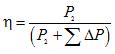
where is the sum of losses in the transformer.
There are two types of losses in a transformer: magnetic losses caused by the passage of magnetic flux through the magnetic circuit and electrical losses resulting from the flow of current through the windings.
Since the magnetic flux of the transformer at U1 = const and the change of the secondary current from zero to nominal practically remains constant, then the magnetic losses in this range of loads can also be assumed constant and equal to the no-load losses.
The electrical losses in the copper of the windings ∆Pm are proportional to the square of the current. It is convenient to express them as short-circuit losses Pcn obtained at rated current,
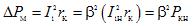
where β is the load factor,

Calculation formulas for determining the transformer efficiency:
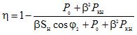
where Sn is the nominal apparent power of the transformer; φ2 is the phase angle between the voltage and current in the load.
The maximum efficiency can be found by equating the first derivative to zero. In this case, we find that the efficiency has maximum values at such a load when the constant (current-independent) losses P0 are equal to the alternating (current-dependent) losses, whence

For modern power oil transformers βopt = 0.5 — 0.7. With such a load, the transformer most often works during operation.
The graph of the dependence η = f (β) is shown in Figure 1.
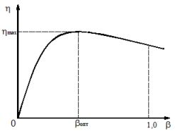
Figure 1. Curve of the change in transformer efficiency depending on the load factor
To determine the percentage change in the secondary voltage of a single-phase transformer, use the equation
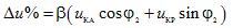
where uKA and uKR are the active and reactive components of the short-circuit voltage, expressed as a percentage.
The change in the transformer voltage depends on the load factor (β), its nature (angle φ2) and the components of the short-circuit voltage (uKA and uKR).
External characteristics of the transformer is the dependence at U1 = const and cosφ2 = const (Figure 2).
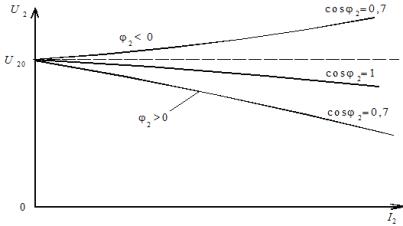
Figure 2. External characteristics of medium and high power transformers for different types of load