Braking modes of asynchronous motors
 An induction motor can operate in the following braking modes: regenerative braking, opposite and dynamic braking.
Regenerative braking of an induction motor
Regenerative braking occurs when the rotor speed of the induction motor exceeds synchronously.
The regenerative braking mode is practically used for pole-changing motors and in the drives of lifting machines (hoists, excavators, etc.).
When switching to generator mode, due to a change in the sign of the torque, the active component of the rotor current changes sign. Then asynchronous engine gives active power (energy) to the network and consumes from the network reactive power (energy) required for excitation. This mode occurs, for example, when stopping (transitioning) a two-speed motor from high to low speed, as shown in fig. 1 a.
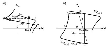
Rice. 1. Stopping of an asynchronous motor in the main commutation circuit: a) with restoration of energy in the network; b) opposition
Suppose that in the initial position the motor operated at characteristic 1 and at point a, rotating at speed ωset1... As the number of pole pairs increases, the motor moves to characteristic 2, the section bs of which corresponds to braking with energy recovery in the network .
The same type of suspension can be implemented in the system frequency converter — motor when stopping an induction motor or when changing from characteristic to characteristic. For this, the frequency of the output voltage is reduced, and hence the synchronous speed ωо = 2πf / p.
Due to mechanical inertia, the current speed of the motor ω will change more slowly than the synchronous speed ωo, and will constantly exceed the speed of the magnetic field. Therefore, there is a shutdown mode with energy return to the grid.
Regenerative braking can also be applied in electric drive of lifting machines when lowering loads. For this, the motor is switched on in the direction of lowering the load (characteristic 2, Fig. 1 b).
After the end of the shutdown, it will work at a point with a speed of -ωset2... In this case, the process of lowering the load is carried out with the release of energy in the network.
Regenerative braking is the most economical type of braking.
Stopping an asynchronous electric motor by opposition
Transferring an induction motor to the opposite braking mode can be done in two ways. One of them is related to a change in the alternation of two phases of the voltage supplying the electric motor.
Assume that the motor operates according to characteristic 1 (Fig. 1 b) with phases of alternating voltage ABC.Then, when switching two phases (e.g. B and C), it goes to characteristic 2, whose section ab corresponds to the opposite stop.
Let's pay attention to the fact that with the opposition asynchronous motor slip ranges from S = 2 to S = 1.
At the same time, the rotor rotates against the direction of motion of the field and constantly slows down. When the speed drops to zero, the motor must be disconnected from the mains, otherwise it can go into motor mode, and its rotor will rotate in the opposite direction to the previous one.
In the case of counter-switching braking, the currents in the motor winding can be 7-8 times higher than the corresponding rated currents. The power factor of the motor decreases significantly. In this case, it is not necessary to talk about efficiency, since both the mechanical energy converted into electricity and the energy consumed by the network are dissipated in the active resistance of the rotor, and in this case there is no useful energy.
Squirrel cage motors are momentarily overloaded with current. It is true that at (S> 1), due to the phenomenon of current displacement, the active resistance of the rotor noticeably increases. This results in a decrease and increase in torque.
To increase the braking efficiency of motors with a wound rotor, additional resistances are introduced into the circuit of their rotors, which makes it possible to limit the currents in the windings and increase the torque.
Another way of reverse braking can be used with the active nature of the torque of the load, which is created, for example, on the motor shaft of the lifting mechanism.
Assume that it is necessary to reduce the load by ensuring its stopping using an induction motor. For this purpose, the motor by including an additional resistor (resistance) in the rotor circuit is transferred to an artificial characteristic (straight line 3 in Fig. 1).
Due to the moment exceeding the load Ms starting torque Mp of the motor and its active nature, the load can be ramped down at a constant rate -ωset2… In this mode, the sliding stop of the induction motor can vary from S = 1 to S = 2.
Dynamic braking of an induction motor
To dynamically stop the stator winding, the motor is disconnected from the AC mains and connected to a DC source as shown in fig. 2. In this case, the rotor winding can be short-circuited, or additional resistors with a resistance of R2d are included in its circuit.
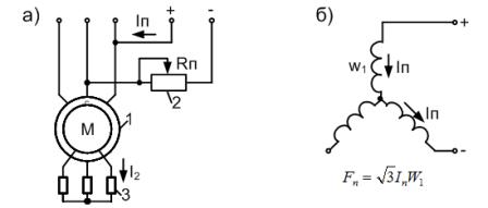
Rice. 2. Scheme of dynamic braking of an induction motor (a) and circuit for turning on the stator windings (b)
The constant current Ip, the value of which can be controlled by resistor 2, flows through the stator windings and creates a stationary magnetic field relative to the stator. When the rotor rotates, an EMF is induced in it, the frequency of which is proportional to the speed. This EMF, in turn, causes a current to appear in the closed loop of the rotor winding, which creates a magnetic flux that is also stationary relative to the stator.
The interaction of the rotor current with the resulting magnetic field of the induction motor creates a braking torque, due to which the braking effect is achieved.In this case, the engine operates in generator mode independently of the alternating current network, converting the kinetic energy of the moving parts of the electric drive and the working machine into electrical energy, which is dissipated in the form of heat in the rotor circuit.
Figure 2b shows the most common scheme for turning on the stator windings during dynamic braking. The engine excitation system in this mode is asymmetrical.
In order to analyze the operation of an induction motor in dynamic braking mode, an asymmetric excitation system is replaced by a symmetric one. For this purpose, it is assumed that the stator is supplied not by a direct current Ip, but by some equivalent three-phase alternating current that creates the same MDF (magnetomotive force) as the direct current.
The electromechanical and mechanical characteristics are shown in Fig. 3.
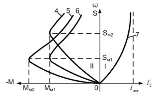
Rice. 3. Electromechanical and mechanical characteristics of the asynchronous motor
The characteristic is found in the figure in the first quadrant I, where s = ω / ωo — slip of an induction motor in dynamic braking mode. The engine's mechanical data is found in the second quadrant II.
Various artificial characteristics of the induction motor in dynamic braking mode can be obtained by changing the resistance R2d additional resistors 3 (Fig. 2) in the rotor circuit or a direct current Azp is supplied to the stator windings.
Variable values R2q and Azn, it is possible to obtain the desired shape of the mechanical characteristics of the induction motor in dynamic braking mode and thus the corresponding braking intensity of the induction electric drive.
A. I. Miroshnik, O. A. Lysenko