How are synchronous turbos and hydrogenerators arranged?
In hydroelectric power plants, generators are driven by water turbines that rotate at speeds of 68 to 250 rpm. In thermal power plants, electrical energy is generated by turbine units consisting of a steam turbine and a turbine generator. For better use of steam energy, turbines are built as high-speed turbines with a rotation speed of 3000 rpm. Thermal plants are also available in large industrial enterprises.
Alternators are simpler in design and can be built with significantly more power than DC generators.
Most synchronous machines use an inverted design compared to DC machines, i.e. the excitation system is located on the rotor and the armature winding on the stator. This is due to the fact that it is easier to supply a relatively low current to the excitation coil through sliding contacts than to supply current to the operating coil. The magnetic system of a synchronous machine is shown in Fig. 1.
The excitation poles of the synchronous machine are located on the rotor.The pole cores of electromagnets are made in the same way as in direct current machines. On the stationary part, the stator, there is a core 2, made of insulated sheets of electrical steel, in the channels of which there is a working coil for alternating current - usually three-phase.
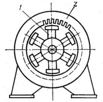
Rice. 1. Magnetic system of a synchronous machine
When the rotor rotates, an alternating emf is induced in the armature winding, the frequency of which is directly proportional to the speed of the rotor. The alternating current flowing through the working coil creates its own magnetic field. The rotor and the field of the working coil rotate at the same frequency — synchronously… In the motor mode, the rotating working field carries with it the magnets of the excitation system, and in the generator mode, vice versa.
See here for more details: Purpose and arrangement of synchronous machines
Consider designing the most powerful machines — turbos and hydrogenerators... Turbine generators are driven by steam turbines, which are most economical at high speeds. Therefore, turbine generators are made with a minimum number of poles of the excitation system — two, which corresponds to a maximum rotation speed of 3000 rpm at an industrial frequency of 50 Hz.
The main problem of turbogenerator engineering is the creation of a reliable machine with the limit values of electrical, magnetic, mechanical and thermal loads. These requirements leave an imprint on the entire design of the machine (Fig. 2).
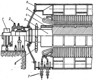
Rice. 2. General view of the turbine generator: 1 — slip rings and brush apparatus, 2 — bearing, 3 — rotor, 4 — rotor strip, 5 — stator winding, 6 — stator, 7 — stator windings, 8 — fan.
The rotor of a turbine generator is made in the form of a solid forging with a diameter of up to 1.25 m, a length of up to 7 m (working part). The total length of the forging, taking into account the shaft, is 12 — 15 m. Channels are milled on the working part, in which the excitation coil is placed. Thus, a cylindrical bipolar electromagnet without clearly defined poles is obtained.
In the production of turbine generators, the latest materials and design solutions are used, in particular, direct cooling of the active parts by jets of a cooling agent - hydrogen or liquid. In order to obtain high power, it is necessary to increase the length of the machine, which gives it a very special look.
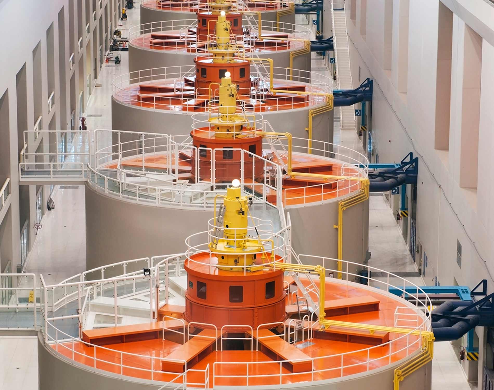
Hydro generators (Fig. 3) differ significantly in construction from turbine generators. The efficiency of the operation of the hydraulic turbine depends on the speed of the water flow, i.e. effort. It is impossible to create high pressure on flat rivers, therefore the rotational speeds of the turbine are very low — from tens to hundreds of revolutions per minute.
To obtain an industrial frequency of 50 Hz, such low-speed machines must be made with a large number of poles. To accommodate a large number of poles, it is necessary to increase the diameter of the rotor of the hydrogenerator, sometimes up to 10-11 m.
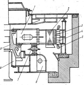
Rice. 3. Longitudinal section of an umbrella hydrogen generator: 1 — rotor hub, 2 — rotor rim, 3 — rotor pole, 4 — stator core, 5 — stator winding, 6 — cross beam, 7 — brake, 8 — thrust bearing, 9 — rotor sleeve.
Building powerful turbos and hydro generators is an engineering challenge.It is necessary to solve a number of issues of mechanical, electromagnetic, thermal and ventilation calculations and to ensure the manufacturability of the structure in production. Only powerful design and production teams and companies can handle these tasks.
Structures of different types are very interesting. synchronous micromachines, in which permanent magnet and reactive systems are widely used, i.e. systems in which the working magnetic field interacts not with the excitation magnetic field, but with the ferromagnetic salient poles of the rotor, which do not have a winding.
Yet the main technological area where synchronous machines have no competitors today is energy. All generators in power plants, from the most powerful to the mobile ones, are based on synchronous machines.
As for synchronous motors, then their weak spot is the startup problem. By itself, a synchronous motor usually cannot accelerate. To do this, it is equipped with a special starting coil working on the principle of an asynchronous machine, which complicates the design and the starting process itself. Synchronous motors are therefore generally available in medium to high power ratings.
The figure below shows the construction of a turbine generator.
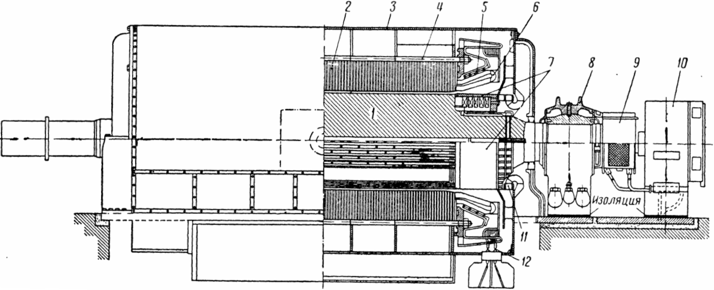
The rotor 1 of the generator is made of steel forging, in which grooves are milled for the excitation coil, driven by a special DC machine 10, called an exciter. The current to the rotor winding is supplied through slip rings closed by the housing 9, the wires of the rotor winding are connected to them.
When rotating, the rotor produces a large centrifugal force.In the grooves of the rotor, the winding is held by metal wedges, and the steel retaining rings 7 are pressed against the front parts.
The stator is assembled from stamped sheets 2 of special electrical steel, which are reinforced in a frame 3 welded from sheet steel. Each stator leaf consists of several parts, called segments, which are fixed with 4 bolts.
In the channels of the stator, a coil 6 is laid, in the wires of which electromotive forces are induced when the rotor rotates. The electromotive forces of the series-connected winding wires increase and a voltage of several thousand volts is generated at the terminals 12. When currents flow between the winding wires, large forces are created. Therefore, the front parts of the stator winding are connected by rings 5.
The rotor rotates in bearings 8. Between the bearing and the base plate is laid a circuit-breaking insulation, through which the bearing currents can be closed. The second bearing is made together with a steam turbine.
To cool the generator, the stator is divided into separate packages, between which ventilation ducts are located. The air is driven by fans 11 mounted on the rotor.
In order to cool powerful generators, it is necessary to push a huge amount of air through them, reaching tens of cubic meters per second.
If the cooling air is taken from the premises of the station, then with the presence of the most insignificant amounts of dust (a few milligrams per cubic meter) in it, the generator will be contaminated with dust in a short time. Therefore, turbine generators are built with a closed ventilation system.
The air, which is heated when passing through the ventilation channels of the generator, enters special air coolers located under the casing of the turbine generator.
There, the heated air passes between the finned tubes of the air cooler, through which water flows, and is cooled. The air is then returned to the fans, which propel it through the ventilation ducts. In this way, the generator is continuously cooled with the same air and dust cannot get inside the generator.
The speed along the circumference of the rotor of a turbine generator exceeds 150 m / s. At this speed, a large amount of energy is expended on the friction of the rotor in the air. For example, in a turbine generator with a power of 50,000 kWVt, energy losses due to air friction are 53% of the sum of all losses.
To reduce these losses, the internal space of the powerful turbine generators is filled not with air, but with hydrogen. Hydrogen is 14 times lighter than air, that is, it has a similar lower density, due to which rotor friction losses are significantly reduced.
In order to prevent an explosion of oxyhydrogen, formed from a mixture of hydrogen and oxygen in air, a higher than atmospheric pressure is set inside the generator. Therefore, atmospheric oxygen cannot penetrate the generator.
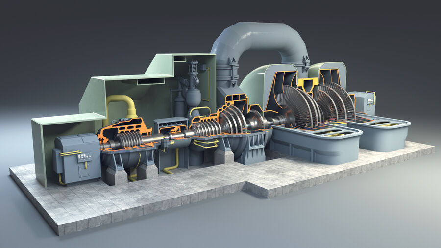
3D model of a steam turbine generator:
Educational tape created by the school supplies factory in 1965:
Synchronous generators