How is the precise stopping of the moving parts of metal cutting machines ensured?
 In the schemes of automatic control of the operation of machines, installations and machines, the issue of the accuracy of stopping the moving units of metal-cutting machines with the help of road switches is very important. In some cases, the accuracy of manufacturing a part depends on it.
The accuracy of braking depends on:
2) the degree of its wear and tear;
3) the state of his contacts;
4) the accuracy of the production of the cam acting on the motion switch;
5) cam adjustment accuracy;
6) the path traveled by the tool during operation of the relay-contactor control devices;
7) the amount of movement of the tool due to the inertial forces of the supply chain;
8) insufficiently accurate coordination of the initial positions of the cutting tool, the measuring device and the track controller;
9) the rigidity of the technological system machine — device — tool — part;
10) the size of the allowance and the properties of the processed material.
The factors specified in clauses 1 — 5 determine the error Δ1 due to inaccuracy in the supply of the command pulse; the factors noted in paras. 6 and 7, — error Δ2 size due to inaccuracy in the execution of the command; the factor specified in point 8 is the error Δ3 alignment of the initial positions of the cutting and measuring tools and the command element of the device; the factors specified in clauses 9 and 10 determine the error Δ4 occurring in each machine due to elastic deformations caused in the technological system by cutting forces.
Total error Δ = Δ1 + Δ2 + Δ3 + Δ4.
 The total error, like its components, is not a constant value. Each of the errors contains systematic (nominal) and random errors. The systematic error is a constant value and can be taken into account during the tuning process. As for random errors, they are caused by random fluctuations in voltage, frequency, friction forces, temperature, the influence of vibration, wear, etc.
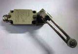
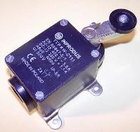
In order to ensure high braking accuracy, errors are sought to be reduced and stabilized as much as possible. One way to reduce the Δ1 error is to increase the accuracy of the motion switches and reduce the travel of the thrusters… For example, micro switches compared to other trajectories used in mechanical engineering, they are distinguished by higher work accuracy.
Even greater accuracy can be achieved using electrical contact heads, which are used to control the dimensions of parts. The accuracy of adjustment of the cams acting on the travel switches can also be increased by using micrometric screws, optical sighting, etc.
Error Δ2, as indicated, depends on the path traveled by the cutting tool after the command is given. When the trip switch is actuated by the stop pushing it at a certain point, the contactor disappears, which takes some time, during which the moving machine block continues to move in section 1 — 2 at the same speed. In this case, fluctuations in speed cause a change in the value of the distance traveled. After disconnecting the electric motor from the contactor, the system decelerates by inertia. In this case, the system passes through the path in section 2 — 3.
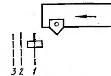
Rice. 1. Precision braking circuit
Resistance moment MC in power circuits is created mainly by frictional forces. During the momentum movement, this moment practically does not change. The kinetic energy of the system during inertial motion is exactly equal to the work of the moment Ms (reduced to the motor shaft) along the angular path φ the motor shaft corresponding to the inertial motion of the system: Jω2/ 2 = Makφ, hence φ = Jω2/ 2 ms
Knowing the transmission ratios of the kinematic chain, it is easy to determine the magnitude of the linear displacement of the translationally moving machine block.
The moment of resistance in the supply chains, as mentioned above, depends on the weight of the device, the condition of the friction surfaces, the quantity, quality and temperature of the lubricant. Fluctuations in these variable factors cause significant changes in the value of Mc and, therefore, in paths 2 — 3. Contactors controlled by path switches also have dispersion in response times. In addition, the movement speed can also vary slightly.All this leads to propagation at breakpoint 3 positions.
 In order to reduce the inertial travel distance, it is necessary to reduce the travel speed, the moment of the flywheel of the system and increase the braking moment. The most effective is deceleration of the drive before stopping... In this case, the kinetic energy of the moving masses and the size of the inertial displacement are sharply reduced.
Reducing the feed rate also reduces the distance traveled during the operation of the devices. However, feed reduction during processing is generally unacceptable as it results in a change in target mode and surface finish. Therefore, reducing the speed of an electric drive is often used when installation movements... The speed of the electric motor is reduced in various ways. In particular, special schemes are used that provide so-called crawling speeds.
The main part of the moment of inertia of the power chain is the moment of inertia of the rotor of the electric motor, therefore, when the electric motor is switched off, it is advisable to mechanically separate the rotor from the rest of the kinematic chain. This is usually done by an electromagnetic clutch… In this case, braking is very fast because the lead screw has a small moment of inertia. The accuracy of braking in this case is mainly determined by the size of the gaps between the elements of the kinematic chain.
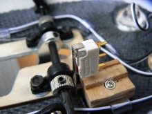
To increase the braking torque, apply electric braking of electric motorsas well as mechanical braking using electromagnetic clutches.Higher stopping accuracy can be achieved by using hard stops that mechanically stop the movement. The disadvantage in this case is the significant forces arising in parts of the system in contact with the rigid limiter. These two types of braking are used together with primary converters that shut down the drive when the pressure on the limiter reaches a certain value. Precise braking using low-voltage electric brakes is schematically shown in Fig. 2.
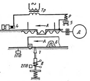
Rice. 2. Precise closing circuits
The movable block A of the machine meets on its way a fixed stop 4. The head of this stop is isolated from the bed of the machine, and when block A comes into contact with it, the circuit of the secondary winding of the transformer Tr closes. In this case, the intermediate relay P is activated, which switches off the motor. Since in this case the machine bed is included in the electrical circuit, the voltage of the circuit is lowered by the transformer Tr to 12 — 36 V. The choice of material that insulates the head of the electrical support is a significant difficulty. It must be strong enough to support its size and at the same time withstand the significant shock loads of the stop 4.
You can also use a hard mechanical stop and a travel switch that shuts off the motor when there are a few fractions of a millimeter left before the device makes contact with the stop, and the travel to the stop is completed by coasting.In this case, it should be borne in mind that the frictional forces are not constant, and if the electric motor is turned off too early by the road switch, the unit may not reach the stop, and if it is late, it will hit the stop.
For particularly precise positioning movements, use an electromagnetically controlled lock... In this case, when the mass A moves, the motion switch 1PV is first activated, which switches the electric motor to run at a reduced speed. At this speed, the socket 6 approaches the catch 7. When the catch 7 falls, the 2PV travel switch is activated and disconnects the electric motor from the mains. When the coil of the electromagnet 8 is turned on, the lock is removed from the socket.
It should be noted that the relative complexity of accurately stopping the moving parts of the machine by means of electro-automation on the track in many cases forces the use of hydraulic systems... In this case, low speeds are relatively easily achieved and the movable block can remain pressed against the hard stop for a long time. Gears such as the Maltese cross and locks are often used for precise stopping during rapid rotation of machine parts.