Electronic time relays
 Electronic watches have been developed to replace them time relay with electromagnetic and mechanical delay… The first electronic time relays were produced based on transistor circuits. After that, integrated circuits began to be used in electronic relays, and later there was a transition to microcontrollers.
In general, any electronic time relay is a device controlled by an input (supply) voltage and switching its output contacts with a specified time delay.
The synchronizing block of most electronic time relays is based on RC circuits (Fig. 1, a). The change in voltage across the capacitor of an RC circuit connected to a DC voltage source is described by an exponential function of time. This allows, by monitoring the capacitor voltage, to form the set time intervals, for example, from the moment the RC circuit is connected to the source until the capacitor voltage reaches the specified level. An exponential function is also used to discharge the pre-charged capacitor of the parallel RC circuit.Such circuits are used in time relays that must switch their contacts after a loss of supply voltage.
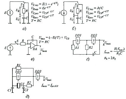
Rice. 1. Variants of timing schemes used in electronic time relays
In some time relays, the charge of the capacitor of the RC-circuit is used with a stable current (Fig. 1, b and c). In this case, the voltage in the capacitor changes linearly with time, which makes it possible to get a little more accuracy in the formation of time delays. The role of a stable current source in such relays is performed by an electronic circuit. However, time relays with a stable current source are more difficult to implement and are therefore not widely used.
The charging (discharging) time of an RC circuit in real circuits does not exceed a few seconds. This is due to several circumstances. First, the resistance of the timing resistor in the RC circuit must be limited (within a few megohms) so that the charge on the capacitor is not affected by the leakage currents through the insulation material of the printed circuit board and the input currents of a circuit that controls the voltage in the capacitor.
Secondly, in the RC circuit it is necessary to use capacitors with minimum charge adsorption. Otherwise, the property of the capacitor to restore the voltage on the plates after its short-term discharge will lead to a distribution in the time at which the relay is ready to work again. Unfortunately, manufactured capacitors with minimal charge adsorption have relatively low capacitance (of the order of a few microfarads).
Relays with short time delays can be implemented based on a single charge (discharge) cycle of the RC circuit.If it is necessary to provide long time delays, the relays are made on the basis of multiple charge-discharge circuits of the RC circuit. In such multi-cycle timing relays, the RC circuit is included in a self-oscillating circuit that provides periodic charge-discharge of its capacitor... For example, a self-oscillating circuit based on an RC circuit can be implemented on logic gates as shown in Fig. 1, year
The charging and discharging of the capacitor C occurs through the resistor R2 due to different voltage levels at the input and output of the inverting logic element DD2. The state of the logic element DD2 is switched by the same logic element DD1, but it is used as a threshold voltage body (the circumstance is realized that the logic elements of the IC go to the state of logic zero and vice versa, at different levels of the input voltage). Thus, when powered, a sequence of pulses with a fairly stable period is formed at the output DD2. By counting the output pulses from the beginning of the self-oscillating circuit, it is possible to obtain an electronic relay with a large range of time delays at relatively small values of the time timing chain constant.
The highest accuracy is provided by electronic time relays with self-oscillating circuits based on quartz resonators (see Fig. 1, e).
The use of low voltage and low current electronic components in electronic time relays necessitates the use of interfaces with external input and output circuits in them.
Structural diagrams of one-time and multi-cycle time relays are shown in fig. 2, a and b respectively.Both circuits include identical blocks: an input converter, a unit for setting the time circuit in its initial state, and an executive (output) body.
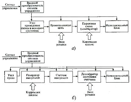
Rice. 2. Block diagrams of time relays
The purpose of the input converter is to form a low voltage with a normalized level to power the synchronizing circuit, as well as to create the reference potentials necessary for the operation of the threshold organs.
The node for setting the time circuit in its initial state is necessary to bring all the relay elements involved in the formation of the time delay to a strictly defined initial mode. Initialization of the relay can be done either at the end of the previous cycle of the relay or at the moment when the relay is energized.
In single-delay relays, the time is adjusted either by changing the time constant of the synchronizing circuit or by changing the threshold of the comparator (threshold organ), which compares the voltage in the capacitor of the synchronizing circuit with the setting and acts on the output (executive) organ.
In multi-cycle time relays, the delay, as a rule, is provided by counting the pulses of the clock generator in the pulse counter and is corrected (to compensate for the dispersion of the parameters of the elements) by changing the time constant RC-chains of the clock generator. When the supply voltage is applied, the clock generator starts and pulses start arriving at the input of the counter.
Recognition of reaching the required state of the counter is provided by a circuit for decoding its state based on mechanical switches that set the set value.At the moment of accumulation in the counter of a certain number of pulses, which coincides with the setting of the decoder, a control signal is generated for the output executive unit.
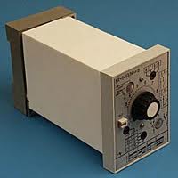
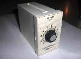
Rice. 3. Electronic time relay VL-54
In recent years, microcontroller-based electronic time relays have been implemented. A microcontroller requires clock pulses with a sufficiently stable frequency to operate. As a rule, these pulses are formed by a built-in oscillator based on quartz resonators (Fig. 1, e). When the timing relay start signal is received, the microcontroller starts counting the clock pulses. Unlike electronic time relays based on RC circuits, the time delays of quartz time relays are practically independent of ambient temperature and relay supply voltage.
A significant advantage of a time relay using microcontrollers is the ability to program them directly in the assembled device. Electronic time relays using software-removed microcontrollers require no setup and start working as soon as power is applied.
The most common indoor electronic time relays: RV-01, RV-03, RP-18, VL-54, VL-56, RVK-100, RP21-M-003
Shumriev V. Ya. Semiconductor time relays.