Electrical equipment of milling machines
 Milling machines are designed for processing external and internal flat and shaped surfaces, cutting, cutting external and internal threads, gears, etc. A feature of these machines is a working tool — a milling cutter with many cutting blades. The main movement is the rotation of the cutter, and the feed is the movement of the product together with the table on which it is fixed. During machining, each cutting edge removes chips during a portion of the cutter's revolution, and the chip cross-section changes continuously from the smallest to the largest. There are two groups of cutters: general purpose (e.g. horizontal, vertical and longitudinal milling) and specialized (e.g. copy milling, gear milling).
Depending on the number of degrees of freedom of movement of the table, there are cantilever milling (three movements - longitudinal, transverse and vertical), non-cantilever milling (two movements - longitudinal and transverse), longitudinal milling (one movement - longitudinal) and rotary milling (single motion — circular feed) machines.All these machines have the same main drive for the rotary movement of the spindle and different drive devices.
Copy-milling machines are used to process spatially complex planes by copying according to templates. As an example, we can point to the surfaces of dies, press molds, impellers of hydraulic turbines, etc. With universal machines, the processing of such surfaces is too complicated or even impossible. A variety of these most common machines are electrocopiers with electrical follow-up control.
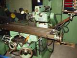
The device of the universal milling cutter 6H81 is shown in Figure 1. The machine is designed for milling various parts of relatively small sizes.
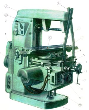
Rice. 1 The device of the universal milling cutter model 6H81
The headstock housing contains the spindle motor, gearbox and cutter spindle. The spindle head moves along the guides of the traverse along its axis, and the traverse, in turn, along a fixed stand with vertical guides.
Thus, the machine has three mutually perpendicular movements: horizontal movement of the table, vertical movement of the spindle head together with the traverse, transverse movement of the spindle head along its axis. Volumetric processing is done with horizontal or vertical lines. Working tool: finger cylindrical and conical or end mills.
The electrical equipment of milling machines includes main drive, power supply, auxiliary drives, various electrical devices for control, monitoring and protection, alarm systems and local lighting of the machine.
Electric drive of milling machines
Drive of the main movement of the cutter: asynchronous squirrel-cage motor; asynchronous pole-changing motor. Stop: opposition by electromagnet. Total control range (20 — 30): 1.
Drive mechanism: mechanical from the main drive chain, asynchronous squirrel-cage motor, pole-changing motor (table movement of longitudinal cutters), G-D system (table movement and feed of longitudinal cutter heads), G-D system with EMU (table for movement of longitudinal cutters); tristoral drive, variable hydraulic drive. Total adjustment range 1: (5 — 60).
Auxiliary drives are used for: rapid movement of milling heads, movement of the cross beam (for longitudinal milling cutters); clamping cross bars; cooling pump; lubrication pump, hydraulic pump.
In horizontal milling machines, the flange motors are usually mounted on the back wall of the bed, and in vertical milling machines, they are most often mounted vertically at the top of the bed. The use of a separate electric motor for the feeder greatly simplifies the design of milling machines. This is acceptable when gear cutting is not performed on the machine. Software cycle control systems are common in milling machines. They are used for rectangular shaping. Digital control systems are widely used for machining curved contours.
Bed milling machines typically use separate squirrel cage induction motors and multi-speed gearboxes to drive each of the spindles. The speed adjustment ranges of the spindle drives reach 20:1.The control circuits of the spindle motors, which are not involved in the machining of the part, are turned off by the control switches. Stopping a running spindle drive is done only after a complete stop of the feed. For this purpose, a time relay is installed in the circuit. The feed motor can only be started after the spindle motor is switched on.
The table drive of heavy milling machines should provide a feed from 50 to 1000 mm / min. In addition, it is necessary to quickly move the table at a speed of 2 — 4 m / min and slow movement when setting the machine at a speed of 5 — 6 mm / min . The total speed control range of the desktop drive reaches 1:600.
In heavy longitudinal milling machines, an electric drive is common according to the G-D system with EMP. The electric drives of the vertical and horizontal (side) headrests are similar to the drive of the table, but have much lower power. If simultaneous movement of the head pads is not required, then a common converter block is used for the drives of all pads. This management is simpler and cheaper. The axial movement of the spindles is carried out with the same feed drive. For this, the kinematic chain is switched accordingly. In heavy milling machines with movable gantry beds, a separate electric motor is also used to move it.
To improve the smoothness of the operation of some cutters, flywheels are used. They are usually mounted on the drive shaft of the milling machine.In gear grinding machines, the necessary correspondence between the main motion and the feed motion is provided by mechanically connecting the feed chain to the main motion chain.
Electrical equipment of cutting machines. Main drive: asynchronous squirrel-cage motor. Drive: mechanical from the main drive chain. Auxiliary drives are used for: rapid movement of the clamp and back rail, movement of the milling head, separation of the unit, rotation of the table, cooling pump, lubrication pump, hydraulic unloading pump (for heavy machines).
Special electromechanical devices and interlocks: device for counting the number of cycles, automatic devices for compensating the wear of the tool dimensions.
A number of cutting machines use computing devices. They are used on shaver machines for pass counting, on gear pre-cutting machines, for counting the number of divisions, and for counting the number of machined parts.
In gear forming machines, the main reciprocating motion is done with the help of cranks and eccentric gears. The electrical equipment of gear forming machines is not difficult. Magnetic starters are used with additional control of "joker" (for commissioning). Stopping the drive is most often done by an electromagnet.
In fig. 2. shows the electrical schematic diagram of the model 6R82SH milling machine
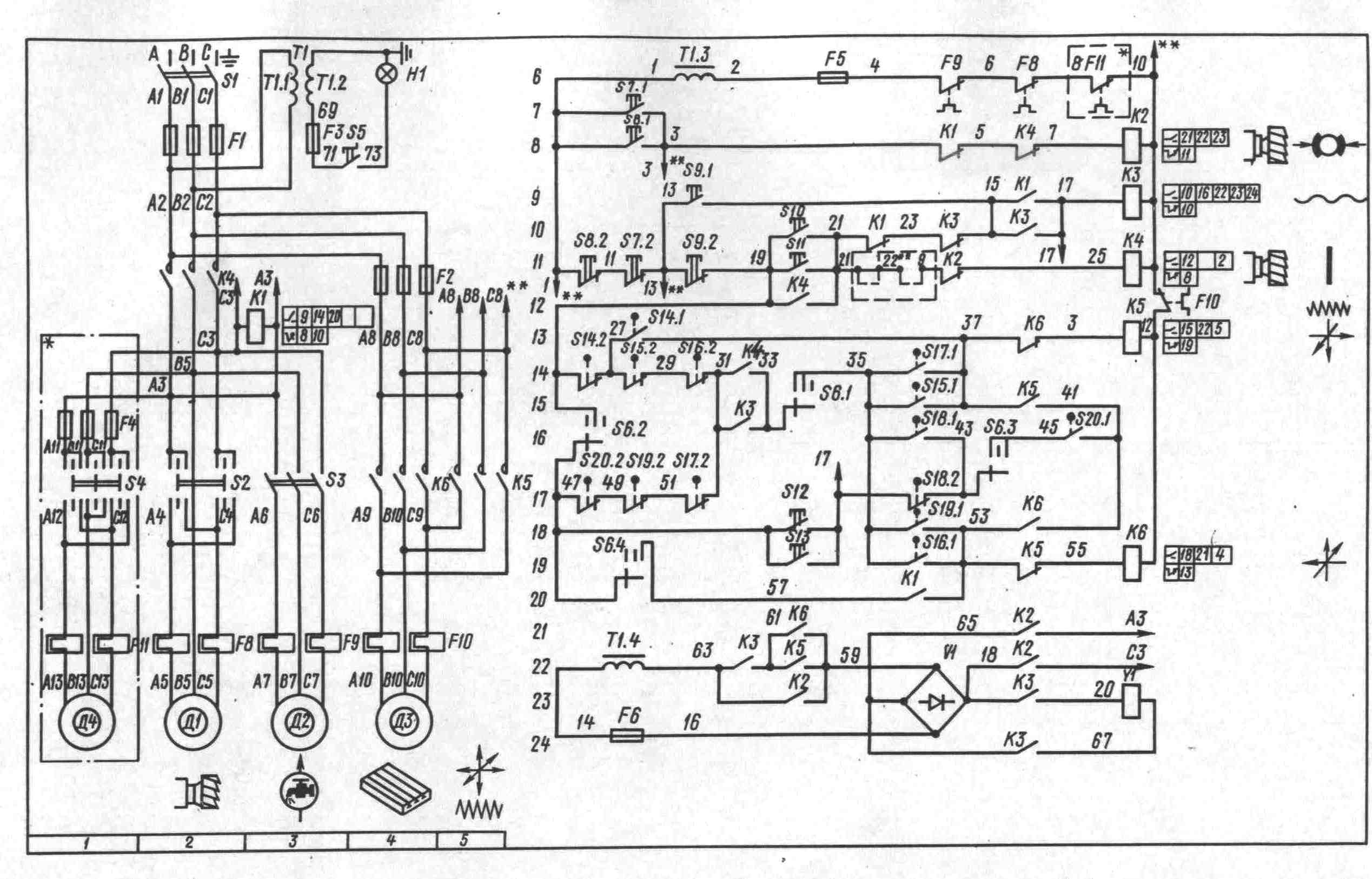
Rice. 2. Electrical schematic diagram of a milling machine (click image to enlarge)
The workplace is illuminated by a local lighting lamp mounted to the left of the machine bed.An electromagnet for rapid movements is located in the console. Control buttons mounted on console brackets and on the left side of the bed. All control devices are located on four panels, on the front side of which the handles of the following controls are displayed: S1 — input switch; S2 (S4) — spindle reversal switch; S6 — mode switch; C3 — cooling switch. The 6R82SH and 6R83SH machines, unlike other machines, have two electric motors to drive the horizontal and the rotary pin cutter.
The electric circuit allows you to work on the machine in the following modes: control by handles and control buttons, automatic control of the longitudinal movements of the table, circular table. The selection of the operating mode is carried out with the switch S6. Switching on and off the feed motor is carried out by the handles acting on the limit switches for longitudinal feed (S17, S19), vertical and transverse feed (S16, S15).
The spindle is switched on and off respectively by the «Start» and «Stop» buttons. When the Stop button is pressed, the feed motor is also turned off when the spindle motor is turned off. The rapid movement of the table occurs when you press the button S12 (S13) «Fast». Spindle motor braking is electrodynamic. When you press the buttons S7 or S8, the contactor K2 turns on, which connects the motor winding to a direct current source made on rectifiers. Buttons S7 or S8 must be pressed until the motor stops completely.
Automatic control of the milling machine is carried out using cams mounted on the table.When the table moves, the cams, acting on the longitudinal feed feed handle and the upper gear, make the necessary switches in the electrical circuit with limit switches. The operation of an electric circuit in an automatic cycle—quick approach—working supply—quick withdrawal. The rotation of the round table is carried out by the feed motor, which is started by the contactor K6 at the same time as the spindle motor. The fast travel of the round table occurs when the «Fast» button is pressed, which turns on the contactor K3 of the high-speed electromagnet.