Electrodynamic and ferrodynamic measuring instruments
 Electrodynamic and ferrodynamic devices are based on the principle of interaction of currents of different coils, one of which is stationary and the other can change its position relative to the first. Electrical energy is supplied to the device's moving coil via coil springs or wires.
Electrodynamic and ferrodynamic measuring devices are used to measure current, voltage, power and other electrical quantities of direct and alternating currents. The scales of voltmeters and ammeters are uneven, and wattmeters are practically the same.
Electrodynamic devices provide the highest accuracy when measuring in alternating current circuits with a frequency of up to 20 kHz, but they do not tolerate overload, differ in significant consumption of electrical energy, and their readings are affected by external magnetic fields.
In order to reduce this influence in devices with a high class of accuracy, shielding and astatic construction of the measuring system are used. The cost of electrodynamic devices is high.
The scale of electrodynamic measuring instruments is often divided into divisions without indicating the values of these divisions in units of measurement. In this case, the device constant, i.e. the number of measured units corresponding to one division of the scale is found by the formulas:
for a voltmeter

for an ammeter

for wattmeter
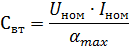
where Unom and Aznom — nominal voltage and current of the device, respectively, αmah — the total number of divisions of the scale.
In electrodynamic ammeters for rated current up to 0.5 A and voltmeters, both windings of the device are connected in series with each other, and in ammeters with a measurement range of more than 0.5 A - in parallel.
Expanding the measurement limits of electrodynamic ammeters is provided by dividing the stationary coil into sections, which allows you to change the measurement range of the device in half, as well as use measuring shunts of direct current and measuring current transformers when measuring in alternating current circuits.
Extending the measurement limits of electrodynamic voltmeters is achieved by using additional resistors, and when measuring in alternating current circuits, in addition, using voltage measuring transformers.
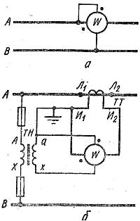
Rice. 1. Schemes for connecting a single-phase wattmeter: a — directly in the network, b — through voltage and current measuring transformers.
Among the electrodynamic measuring devices, the most widespread is a wattmeter (Fig.1, a), in which a fixed coil with a small number of turns of a thick wire is connected in series in the circuit, and a movable one - connected to a built-in housing or to an external additional resistor - in parallel with that section of the circuit in which the power is measured. In order to deflect the wattmeter arrow in the required direction, the rules for turning on the device must be observed: electrical energy must enter the device from the side of the generator terminals of the windings, which are marked on the device with "*".
The scale on each wattmeter indicates the rated voltage and current for which the device is designed. If necessary, it is allowed to bring the voltage and current up to 120% of their nominal values within 2 hours. Some electrodynamic wattmeters have variable measurement ranges for both nominal voltage and nominal current, for example 30/75/150 /300 V and 2.5/5 A.
Current scale expansion of electrodynamic wattmeters is done in the same way as electrodynamic ammeters, and voltage scale expansion is similar to electrodynamic voltmeters. If the electrodynamic wattmeter is turned on through voltage and current measuring transformers (Fig. 1, b), the measured power is found by the formula

where K.ti and Ki — nominal transformation ratios, respectively, of measuring voltage and current transformers, ° СW — wattmeter constant, α — the number of divisions read by the device.
When turned on electrodynamic phase meter in the AC circuit (Fig.2) it is necessary to ensure that the wires supplying power to the device are connected to the generator terminals marked on the device with "*". Such a direct connection is possible if the mains voltage corresponds to the rated voltage of the phasor and the load current does not exceed its rated current. current.
The nominal voltage and current of the phasor are shown on its scale, where there are also designations: «IND» for the part of the scale corresponding to the current lagging the voltage, and «EMK» for the part of the scale corresponding to the leading current. In case the voltage and current of the circuit exceed the corresponding rated voltage and current of the phasor, it should be switched on through the corresponding measuring voltage and current transformers.
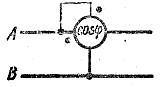
Rice. 2. Circuit diagram of the phase meter.
Ferrodynamic devices are similar to electrodynamic devices, but differ from them in an enhanced magnetic field of a stationary coil due to a magnetic core made of ferrimagnetic material, which increases the torque, increases sensitivity, weakens the influence of external magnetic fields and reduces the consumption of electrical energy. The accuracy of ferrodynamic measuring instruments is lower than the accuracy of electrodynamic instruments. They are also suitable for use on alternating current circuits with a frequency of 10 Hz to 1.5 kHz.
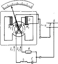
Rice. 3. Schematic diagram of a ferrodynamic frequency counter
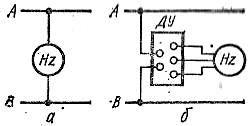
Rice. 4. Scheme of switching on the frequency meter: a — directly in the network, b — through the additional resistance
Ferrodynamic frequency meters are usually connected to an alternating voltage network in parallel or through an additional remote control device (Fig.4, a, b), which is an electric circuit with resistors, inductive coils and capacitors located in a separate housing. When turning on the frequency meter, you should check that the mains voltage corresponds to the nominal voltage of the device, which is indicated on its scale. Ferrodynamic frequency meters are also produced without additional devices for several nominal voltages, each of which corresponds to a specific clamp of the device and a common clamp marked with «*».