Structural forms of asynchronous motors
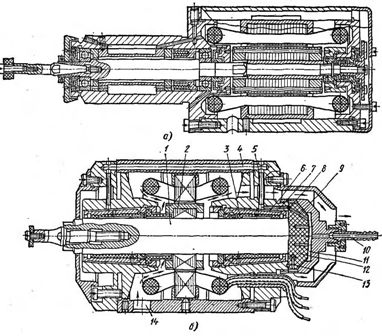
 External structural forms asynchronous motors are determined by the way the engine is mounted and the form of its protection from the influence of the environment. Normal leg motor performance is widespread (Fig. 1, a). In this case, the motor shaft must be horizontal. Engines with flanges (Fig. 1, b) are widely used for horizontal and vertical installations.
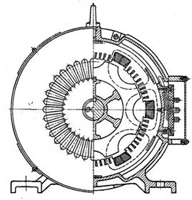
They also produce inline induction motors that have no frame, end shields, shaft. Elements of such a motor are embedded in the parts of the machine body, and the motor shaft is one of the machine shafts (often the spindle), and the bed is the body of the machine assembly, for example, a grinding head (Fig. 2).
Special design motors are widely distributed abroad, including motors with small radial dimensions and considerable length, and disc motors, particularly with a cylinder-shaped stator and a ring-shaped outer rotor. Motors are also used, when they are turned on, the rotor, which has the shape of a cone, moves in an axial direction, developing a significant thrust force.
This force is used to release the mechanical brake acting on the motor shaft after the motor is disconnected from the mains. In addition, numerous engine designs are used with attached gearboxes, gearboxes and mechanical variators that provide smooth regulation.
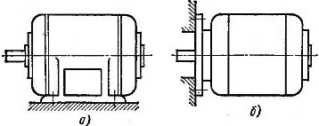
Rice. 1. Design of asynchronous motors
The disadvantage of using engines with special design forms is the difficulty in replacing them in the event of an accident. A faulty electric motor should not be replaced, but repaired, and the machine idled during the repair.
Engines with various forms of environmental protection are used to drive the machines.
Shielded motors have grills that cover the vents on the end shields. This prevents foreign objects from entering the engine and also prevents the worker from touching rotating and live parts. To prevent liquid droplets from falling from above, the engines are equipped with downward or vertical vents.
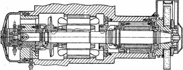
Rice. 2. Built-in grinding motor
However, when such an electric motor works in a workshop, its fan, together with air, sucks in dust, sprays coolant or oil, as well as small particles of steel or cast iron, which, adhering to the insulation of the winding and vibrating under the influence of an alternating magnetic field, quickly wear out the insulation.
Closed engines, whose end screens do not have ventilation holes, have more reliable protection against environmental influences. Such engines, with the same dimensions as protected ones, due to poorer cooling, have less power.With the same powers and speeds, the closed electric motor is 1.5-2 times heavier than the protected one and, accordingly, its price is higher.
The desire to reduce the size and cost of closed motors led to the creation of closed blown electric motors. Such an electric motor has an external fan mounted on the end of the motor shaft opposite the drive end and covered with a cap. This fan blows around the motor housing.
Fan motors are significantly lighter and cheaper than closed ones. Blown motors are most often used to drive metal cutting machines. Engines with other forms of environmental protection are relatively rarely used to drive metal cutting machines. In particular, enclosed electric motors are sometimes used to drive grinding machines.
Electric motors are designed for standard voltages of 127, 220 and 380 V. The same motor can be connected to networks with different voltages, for example, to networks with voltages of 127 and 220 V, 220 and 380 V. with two voltages, the stator winding of the electric motor is connected in a triangle, for a larger one - in a star. The current in the windings of the electric motor and the voltage in them will be the same in both cases with this inclusion. In addition, they produce electric motors 500 V, their stators are permanently connected in a star.
Asynchronous squirrel-cage motors used in many industries are produced with a rated power of 0.6-100 kW per synchronous speeds 600, 750, 1000, 1500 and 3000 rpm.
The cross-section of the wires of the winding of the electric motor depends on the magnitude of the current flowing through it. With a larger current, the motor winding will have a larger volume.The cross-section of the magnetic circuit is proportional to the magnitude of the magnetic flux. In this way, the dimensions of the electric motor are determined by the calculated values of current and magnetic flux or the rated torque of the electric motor. Rated engine power
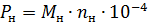
where P.n — nominal power, kW, Mn- nominal moment, N • m, nn- nominal speed, rpm.
Rated power for the same engine size increases as its rated speed increases. Therefore, low-speed electric motors are larger than high-speed motors of the same power.
When grinding small holes, very high grinding spindle speeds are required to obtain adequate cutting speeds. So, when grinding with a wheel with a diameter of 3 mm at a speed of only 30 m / s, the speed of the spindle should be equal to 200,000 revolutions per minute. At high spindle speeds, the clamping force can be reduced sharply. At the same time, wheel grinding and mandrel bending are reduced, and the surface finish and machining accuracy are increased.
In connection with the above, the industry uses numerous models of the so-called. Electric spindles with rotation speeds of 12,000-144,000 rpm and higher. The electrospindle (Fig. 3, a) is a grinding spindle on rolling bearings with a built-in high-frequency squirrel-cage motor. The motor rotor is located between two bearings at the end of the spindle opposite the grinding wheel.
Rice. 3. Electrospindles
The electric spindle stator is assembled from sheet electrical steel. A bipolar coil is placed on it.The motor rotor at speeds up to 30,000-50,000 rpm is also dialed from sheet metal and supplied with a conventional short-circuit winding. They tend to reduce the diameter of the rotor as much as possible.
The choice of bearing type is of particular importance for the operation of electrospindles. Precision ball bearings are commonly used, which operate with a preload created using calibrated springs. Such bearings are used for rotation speeds that do not exceed 100,000 revolutions per minute.
Aerostatic bearings are widely used in industry (Fig. 3, b). The shaft 1 of the high-frequency electric motor rotates in air-lubricated bearings 3. The axial load is absorbed by the air cushion between the end of the shaft and the support bearing 12, against which the shaft is pressed under the pressure of the air supplied to the interior of the housing through the hole 14 for cooling the engine. The compressed air passes through the filter and enters through the fitting 10 in the chamber 11. From here, through the channel 9 and the circular groove 8, the air passes into the channel 7 and the chamber 6. From there, the air enters the bearing gap. Air is supplied to the left bearing through pipes 5 and channels 4 in the engine housing.
The exhaust air is discharged through the channels 13. The air cushion in the support bearing gap is created by the air passing from the chamber 11 through the bearing made of porous carbon graphite. Each bearing has tapered brass. A carbon graphite liner is pressed into it, the pores of which are filled with bronze. Before starting the electrospindle, air is supplied and air cushions are formed between the spindle and the bushings. This eliminates friction and wear on the bearings during startup.After that, the motor is turned on, the speed of the rotor 2 reaches the nominal speed in 5-10 s. When the engine is turned off, rotor 2 coasts for 3-4 minutes. To reduce this time, an electric brake is used.
The use of air bags drastically reduces the friction losses in the electric spindle, the air consumption is 6-25 m3 / h.
Electrospindles on bearings with liquid lubrication have also been used. Their operation requires continuous circulation of oil under high pressure, otherwise the heating of the bearings becomes unacceptable.
The production of high-frequency electric motors requires precision manufacturing of individual parts, dynamic balancing of the rotor, precise assembly and ensuring strict uniformity of the gap between the stator and the rotor. The frequency of the current supplying the high-frequency electric motor is selected depending on the required speed of the electric motor:

where nIf the synchronous frequency of rotation of the electric motor, rpm, f is the frequency of the current, Hz, p is the number of poles, since p = 1, then

At synchronous rotation speeds of the electric spindles of 12,000 and 120,000 rpm, the current frequency should be equal to 200 and 2000 Hz, respectively.
Special generators are used to power high-frequency motors. In fig. 4 shows a three-phase synchronous induction generator. The generator stator has wide and narrow slots. The field coil, which is located in the wide slots of the stator, is supplied with direct current. The magnetic field of the conductors of this coil is closed through the stator teeth and rotor protrusions as shown in fig. 4 with dotted line.
When the rotor rotates, the magnetic field moving along the rotor protrusions crosses the turns of the alternating current winding located in the narrow slots of the stator and induces an alternating e. etc. c. The frequency of this e. etc. v. depends on the speed and number of rotor ears. The electromotive forces induced by the same flux in the field-wound windings cancel each other due to the impending activation of the coils. The field coils are powered by a rectifier connected to the mains. The stator and rotor have magnetic cores made of sheet electrical steel.
Rice. 4. High frequency induction generator
Generators with the described design are produced for nominal power from 1 to 3 kW and frequencies from 300 to 2400 Hz. The generators are driven by asynchronous motors with a synchronous speed of 3000 rpm.
Induction generators with increased frequency are beginning to be replaced by semiconductor (thyristor) converters. In this case, they usually provide the ability to change the frequency of the current and therefore the ability to adjust the speed of rotation of the electric motor. If during such regulation the voltage is kept constant, then constant power regulation is performed. If the ratio of voltage to frequency of the current (and therefore the magnetic flux of the motor) is kept constant, then the regulation is carried out with a constant at all speeds for a long time permissible torque.
The advantages of drives with a thyristor frequency converter and asynchronous squirrel-cage motor are high efficiency and ease of use. The downside is still the high price.In mechanical engineering, it is most recommended to use such a drive for high-frequency motors. Experimental drives of this type have been created in our country.
Low-power two-phase asynchronous motors are often used in machine tool executive drives. The stator of such a motor has two windings: field winding 1 and control winding 2 (Fig. 5, a). Rotor 4 in a squirrel cage has a large active resistance. The axis of the coils are perpendicular to each other.
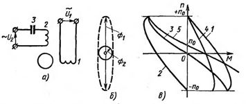
Rice. 5. Scheme of a two-phase induction motor and its characteristics
Voltages Ul and U2 are applied to the windings. When the capacitor 3 is connected to the circuit of the coil 2, the current in it exceeds the current in the coil 1. In this case, a rotating elliptical magnetic field is formed and the rotor 4 of the squirrel starts to rotate. If you reduce the voltage U2, the current in coil 2 will also decrease. This will lead to a change in the shape of the ellipse of the rotating magnetic field, which becomes more and more elongated (Fig. 5, b).
An elliptical field motor can be considered as two motors on one shaft, one operating with a pulsating field F1 and the other with a circular field F2. The F1 pulsating-field motor can be thought of as two identical circular-field induction motors wired to rotate in opposite directions.
In fig. 5, c shows the mechanical characteristics 1 and 2 of an induction motor with a circular rotating field and a significant active resistance of the rotor when rotating in different directions. The mechanical characteristic 3 of a single-phase motor can be constructed by subtracting the moments M of characteristics 1 and 2 for each value of n.At any value of n, the torque of a single-phase motor with high rotor resistance is stopped. The mechanical characteristic of the circular field motor is represented by curve 4.
The mechanical characteristic 5 of a two-phase motor can be constructed by subtracting the moments M of characteristics 3 and 4 at any value of n. The value of n0 is the rotational speed of a two-phase induction motor at ideal idle speed. By adjusting the supply current of coil 2 (Fig. 5, a), it is possible to change the slope of characteristic 4 (Fig. 5, c), and hence the value of n0. In this way, the speed control of a two-phase induction motor is carried out.
When operating with high slip values, losses in the rotor become quite significant. For this reason, the considered regulation is only used for low power auxiliary drives. To reduce the acceleration and deceleration time, two-phase induction motors with a hollow rotor are used. In such an engine, the rotor is a thin-walled aluminum hollow cylinder.